Content .. 1106 1107 1108 1109 ..
Nissan Rogue. Manual - part 1108
SPIRAL CABLE
SR-15
< REMOVAL AND INSTALLATION >
C
D
E
F
G
I
J
K
L
M
A
B
SR
N
O
P
SPIRAL CABLE
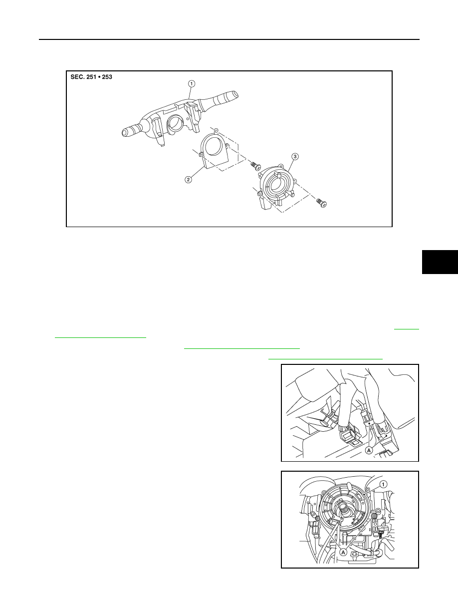
Exploded View
INFOID:0000000011279756
Removal and Installation
INFOID:0000000011279757
WARNING:
• Before servicing the SRS, turn ignition switch OFF, disconnect both battery terminals then wait at
least three minutes.
• Do not use the air tools or electric tools for servicing.
REMOVAL
1. Disconnect the negative and positive battery terminals, then wait at least three minutes. Refer to
2. Remove the steering wheel. Refer to
ST-11, "Removal and Installation"
.
3. Remove the steering column upper and lower cover. Refer to
IP-18, "Removal and Installation"
4. Disconnect harness connectors (A).
5. Remove screws (A) and then remove spiral cable (1).
ALHIA0359ZZ
1.
Combination switch
2.
Steering angle sensor
3.
Spiral cable
ALHIA0351ZZ
ALHIA0350ZZ