Nissan Maxima. Manual - part 735


  Index      Nissan     Nissan Maxima (2009-2014 year) - Service and Repair Manual


Search            


Content   ..  733  734  735  736   ..


Nissan Maxima. Manual - part 735


HAC-116

< SYSTEM DESCRIPTION >

[WITH MONOCHROME DISPLAY]

AUTOMATIC AIR CONDITIONER SYSTEM

FRESH AIR (

) SWITCH

• When the FRE switch is ON, the FRE switch indicator is turned ON, and air inlet is set to FRE.

DUAL MODE SWITCH

• When the DUAL switch indicator is ON, the driver side and passenger side temperature can each be set

independently.

• When the DUAL switch indicator is OFF, the driver side outlet and setting temperature are applied to both

sides.

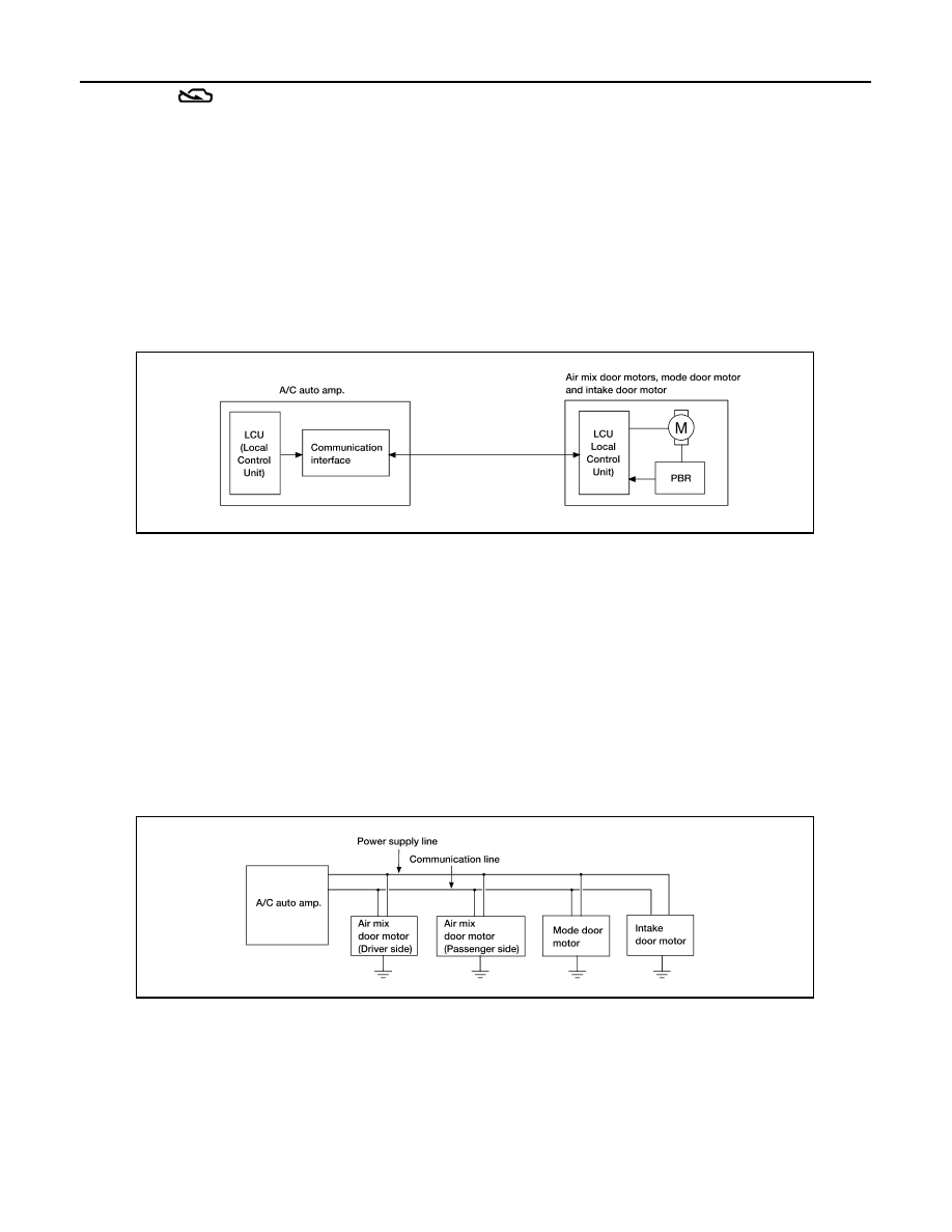
Air Conditioner LAN Control System

INFOID:0000000010051114

The LAN (Local Area Network) system consists of the A/C auto amp., the mode door motor, the air mix door

motors and the intake door motor.

A configuration of these components is as shown in the figure below.

SYSTEM CONSTRUCTION

A small network exists between the A/C auto amp., the mode door motor, the air mix door motors and the

intake door motor. The A/C auto amp. and motors are connected by data transmission lines and motor power

supply lines. The LAN network is built through the ground circuits of each door motor.

Addresses, motor opening angle signals, motor stop signals and error checking messages are all transmitted

through the data transmission lines connecting the A/C auto amp. and each door motor.

The following functions are contained in LCUs built into the mode door motor, the air mix door motors and the

intake door motor.

• Address

• Motor opening angle signals

• Data transmission

• Motor stop and drive decision

• Opening angle sensor (PBR function)

• Comparison

• Decision (A/C auto amp. indicated value and motor opening angle comparison)

Operation

The A/C auto amp. receives data from each of the sensors. The A/C auto amp. sends mode door, the air mix

door and the intake door opening angle data to the mode door motor LCU, the air mix door motor LCUs and

the intake door motor LCU.

The mode door motor, the air mix door motors and the intake door motor read their respective signals accord-

ing to the address signal. Opening angle indication signals received from the A/C auto amp. and each of the

motor position sensors is compared by the LCUs in each door motor with the existing decision and opening

AWIIA1061GB

AWIIA1062GB

AUTOMATIC AIR CONDITIONER SYSTEM

HAC-117

< SYSTEM DESCRIPTION >

[WITH MONOCHROME DISPLAY]

C

D

E

F

G

H

J

K

L

M

A

B

HAC

N

O

P

angles. Next, HOT/COLD, DEF/VENT or FRE/REC operation is selected. The new selection data is returned

to the A/C auto amp.

TRANSMISSION DATA AND TRANSMISSION ORDER

A/C auto amp. data is transmitted consecutively to each of the door motors following the form as shown in the

figure below.

START:

• Initial compulsory signal is sent to each of the door motors.

ADDRESS:

• Data sent from the A/C auto amp. is selected according to data-based decisions made by the mode door

motor, the air mix door motors and the intake door motor.

• If the addresses are identical, the opening angle data and error check signals are received by the door motor

LCUs. The LCUs then make the appropriate error decision. If the opening angle data has no error, door con-

trol begins.

• If an error exists, the received data is rejected and the corrected data is received. Finally, door control is

based upon the corrected opening angle data.

OPENING ANGLE:

• Data that shows the indicated door opening angle of each door motor.

ERROR CHECK:

• In this procedure, transmitted and received data is checked for errors. Error data is then compiled. The error

check prevents corrupted data from being used by the mode door motor, the air mix door motors and the

intake door motor. Error data can be related to the following symptoms:

- Malfunction of electrical frequency

- Poor electrical connections

- Signal leakage from transmission lines

- Signal level fluctuation

STOP SIGNAL:

• At the end of each transmission, a stop operation, in-operation, or internal malfunction message is delivered

to the A/C auto amp. This completes one data transmission and control cycle.

AWIIA1063GB

AWIIA1064GB

HAC-118

< SYSTEM DESCRIPTION >

[WITH MONOCHROME DISPLAY]

AUTOMATIC AIR CONDITIONER SYSTEM

AIR MIX DOOR CONTROL (AUTOMATIC TEMPERATURE CONTROL)

• The air mix doors are automatically controlled so that in-vehicle temperature is maintained at a predeter-

mined value by the temperature setting, ambient temperature, in-vehicle temperature and amount of sun-

load.

FAN SPEED CONTROL

• Fan speed is automatically controlled by the temperature setting, ambient temperature, in-vehicle tempera-

ture, intake temperature, amount of sunload and air mix door position.

With pressing AUTO switch, the blower motor starts to gradually increase air flow volume.

When engine coolant temperature is low, the blower motor operation is delayed to prevent cool air from flow-

ing.

INTAKE DOOR CONTROL

• The intake doors are automatically controlled by the temperature setting, ambient temperature, in-vehicle

temperature, intake temperature, amount of sunload and ON/OFF operation of the compressor.

MODE DOOR CONTROL

• The mode door is automatically controlled by the temperature setting, ambient temperature, in-vehicle tem-

perature, intake temperature and amount of sunload.

MAGNET CLUTCH CONTROL

When A/C switch, AUTO switch or DEF (

) switch is pressed, A/C auto amp. transmits compressor ON sig-

nal to ECM, via CAN communication.

ECM judges whether compressor can be turned ON, based on each sensor status (refrigerant pressure sen-

sor signal, throttle angle, etc.). If it judges compressor can be turned ON, it sends compressor ON signal to

IPDM E/R, via CAN communication.

Upon receipt of compressor ON signal from ECM, IPDM E/R turns air conditioner relay ON to operate com-

pressor.

When sending compressor ON signal to IPDM E/R via CAN communication line, ECM simultaneously sends

compressor feedback signal to A/C auto amp. via CAN communication line.

JPIIA0505GB

MODE DOOR CONTROL SYSTEM

HAC-119

< SYSTEM DESCRIPTION >

[WITH MONOCHROME DISPLAY]

C

D

E

F

G

H

J

K

L

M

A

B

HAC

N

O

P

MODE DOOR CONTROL SYSTEM

System Diagram

INFOID:0000000010051115

System Description

INFOID:0000000010051116

The mode door is automatically controlled by the temperature setting, ambient temperature, in-vehicle temper-

ature, intake temperature and amount of sunload.

SYSTEM OPERATION

• The A/C auto amp. receives data from each of the sensors.

• The A/C auto amp. sends the air mix door, the mode door and the intake door opening angle data to the air

mix door motor LCU(s), the mode door motor LCU and the intake door motor LCU.

• The air mix door motor(s), the mode door motor and the intake door motor read their respective signals

according to the address signal. Opening angle indication signals received from the A/C auto amp. and each

of the motor position sensors, are compared by the LCUs in each door motor with the existing decision and

opening angles.

• Next, HOT/COLD, DEF/VENT or FRE/REC operation is selected. The newly selected data is returned to the

A/C auto amp.

Door Motor Circuit

Mode Door Control Specification

AWIIA1121GB

AWIIA1066GB


Content   ..  733  734  735  736   ..