Nissan Altima HL32 Hybrid. Manual - part 789


  Index      Nissan     Nissan Altima HL32 Hybrid (2009 year) - Service and Repair Manual


Search            


Content   ..  787  788  789  790   ..


Nissan Altima HL32 Hybrid. Manual - part 789


LU-8

< ON-VEHICLE MAINTENANCE >

[QR25DE]

ENGINE OIL

ON-VEHICLE MAINTENANCE

ENGINE OIL

Inspection

INFOID:0000000004211271

OIL LEVEL

• Before turning the Hybrid System ON, check the oil level. If the

Hybrid System is already ON, turn OFF the Hybrid System and

allow 10 minutes before checking.

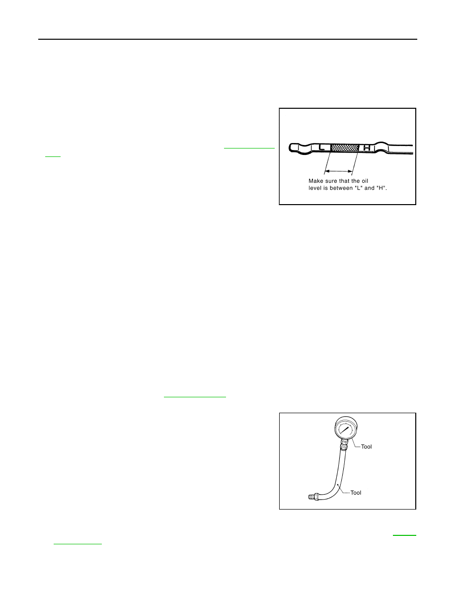
• Check that the oil level is within the range on the dipstick.

• If it is out of range, add oil as necessary. Refer to 

LU-8, "Inspec-

tion"

.

ENGINE OIL APPEARANCE

• Check engine oil for white milky or excessive contamination.

• If engine oil becomes milky, it is highly probable that it is contaminated with engine coolant. Repair or

replace damaged parts.

OIL LEAKAGE

Check for oil leakage around the following areas:

• Oil  pan

• Oil pan drain plug

• Oil pressure switch

• Oil filter

• IVTC cover

• Front cover

• Mating surface between cylinder block and cylinder head

• Mating surface between cylinder head and rocker cover

• Crankshaft oil seal

OIL PRESSURE CHECK

WARNING:

• Be careful not to burn yourself, as engine oil may be hot.

• Put the selector lever in the Park “P” position.
1. Check engine oil level. Refer to 

LU-8, "Inspection"

.

2. Remove undercover using power tool.
3. Disconnect oil pressure switch harness connector at oil pressure

switch. Remove oil pressure switch and install Tools.

CAUTION:

Do not drop or shock oil pressure switch.

4. Turn Hybrid System ON and warm the engine up to normal operating temperature.
5. Check oil pressure with Hybrid System ON and engine running under no-load, using Tool. Refer to 

LU-16,

"Oil Pressure"

.

If difference is extreme, check oil passage and oil pump for oil leaks.

NOTE:

PBIC0249E

Tool numbers : ST25051001 (J-25695-1)

: ST25052000 (J-25695-2)

WBIA0571E

ENGINE OIL

LU-9

< ON-VEHICLE MAINTENANCE >

[QR25DE]

C

D

E

F

G

H

I

J

K

L

M

A

LU

N

P

O

When engine oil temperature is low, engine oil pressure becomes high.

6. After the inspections, install oil pressure switch as follows:
a. Remove old liquid gasket adhering to oil pressure switch and oil cooler.
b. Apply liquid gasket and tighten oil pressure switch to the specification.

Use Genuine RTV Silicone Sealant or equivalent. Refer to 

GI-15, "Recommended Chemical Prod-

ucts and Sealants"

.

c. With the Hybrid System ON and after warming up engine, make sure there are no engine oil leaks with

engine running.

Changing Engine Oil

INFOID:0000000004211272

WARNING:

• Be careful not to burn yourself, as the engine oil may be hot.

• Prolonged and repeated contact with used engine oil may cause skin cancer: try to avoid direct skin

contact with used oil. If skin contact is made, wash thoroughly with soap or hand cleaner as soon as

possible. 

1. Position the vehicle so it is level on the hoist.
2. Turn Hybrid System ON and warm up the engine, and check for oil leaks from the engine.
3. Turn Hybrid System OFF and wait for 10 minutes.
4. Remove the oil pan drain plug and oil filler cap.
5. Drain the engine oil.
6. Install the oil pan drain plug with a new washer and refill the engine with new engine oil.

• Oil specification and viscosity. Refer to 

MA-10, "Fluids and Lubricants"

.

CAUTION:

• Be sure to clean the drain plug and install using a new washer.

• The refill capacity depends on the oil temperature and drain time. Use these specifications for

reference only. Always use the dipstick to determine when the proper amount of oil is in the

engine.

7. Turn Hybrid System ON and warm up the engine and check the area around the drain plug and oil filter for

oil leakage.

8. Turn the Hybrid System OFF and wait for 10 minutes.
9. Check the oil level using the dipstick.

CAUTION:

Do not overfill the engine oil.

Oil pressure switch torque

: 14.8 N·m (1.5 kg-m, 11 ft-lb)

Oil pan drain plug

: Refer to 

EM-31, "Removal and Installation"

.

LU-10

< ON-VEHICLE MAINTENANCE >

[QR25DE]

OIL FILTER

OIL FILTER

Removal and Installation

INFOID:0000000004211273

REMOVAL

1. Remove the oil filter using Tool.

WARNING:

• Be careful not to get burned when the engine and engine

oil are hot.

CAUTION:

• When removing, prepare a shop cloth to absorb any oil

leakage or spillage.

• Do not allow engine oil to adhere to the drive belts.

• Completely wipe off any oil that adheres to the engine and

the vehicle.

• The oil filter has a built in pressure relief valve. Use a gen-

uine NISSAN oil filter or equivalent

INSTALLATION

1. Clean off any foreign materials adhering to the oil filter installation surface.
2. Apply engine oil to the oil seal surface of the new oil filter.

3. Screw the oil filter manually until it touches the installation sur-

face, then tighten it by 2/3 turn. Or tighten to specification below.

4. Check oil level and add engine oil as necessary. Refer to 

LU-8, "Inspection"

.

5. Turn the Hybrid System ON and after warming up the engine, check for oil leaks.

Tool number

: KV10115801 (J-38956)

WBIA0589E

ALC094

SMA010

Oil filter

: 17.6 N·m (1.8 kg-m, 13 ft-lb)

SMA229B

OIL PUMP

LU-11

< ON-VEHICLE REPAIR >

[QR25DE]

C

D

E

F

G

H

I

J

K

L

M

A

LU

N

P

O

ON-VEHICLE REPAIR

OIL PUMP

Removal and Installation

INFOID:0000000004211274

The oil pump is part of the front cover, for removal and installation of the oil pump it is necessary to remove

and install the front cover. Refer to 

EM-51, "Removal and Installation"

.

Disassembly and Assembly

INFOID:0000000004211275

CAUTION:

Before assembly, apply new engine oil to the parts as shown above.

DISASSEMBLY

1. Remove the oil pump cover.
2. Remove inner rotor and outer rotor from front cover. 
3. After removing regulator plug, remove regulator spring and regulator valve.

INSPECTION AFTER DISASSEMBLY

Measure the clearance of the oil pump parts to check they are within specification.
1. Measure clearance with feeler gauge as follows:

• Clearance between outer rotor and oil pump body (position 1).

• Tip clearance between inner rotor and outer rotor (position 2).

KBIA0153E

1.

Front cover

2.

Outer rotor

3.

Inner rotor

4.

Oil pump cover

5.

Regulator valve

6.

Spring

7.

Regulator plug

Standard

: 0.114 - 0.179 mm (0.0045 - 0.0070 in)

Standard

: 0.170 - 0.220 mm (0.0067 - 0.0087 in)

SLC932A


Content   ..  787  788  789  790   ..