Nissan Altima HL32 Hybrid. Manual - part 673
P0ADB-227, P0ADC-226
HBC-441
< COMPONENT DIAGNOSIS >
D
E
F
G
H
I
J
K
L
M
A
B
HBC
N
O
P
OK or NG
OK
>> GO TO 7.
NG
>> Repair or replace harness or connector.
7.
CHECK HARNESS AND CONNECTOR
CAUTION:
Be sure to wear insulated gloves.
1. Connect the battery pack wire connector.
2. Measure the resistance according to the value(s) in the table
below.
OK or NG
OK
>> GO TO 8.
NG
>> Repair or replace harness or connector.
8.
INSPECT HV RELAY ASSEMBLY (SMRB)
CAUTION:
Be sure to wear insulated gloves and protective goggles.
1. Check that the service plug grip is not installed.
2. Remove the HV relay assembly from the vehicle (See
HBB-105, "Removal and Installation"
).
3. Measure the resistance according to the value(s) in the table
below.
4. Measure the resistance according to the value(s) in the table
below.
OK or NG
OK
>> Replace hybrid vehicle control ECU (See
HBC-644, "Removal and Installation"
).
NG
>> Replace HV relay assembly (See
HBB-105, "Removal and Installation"
).
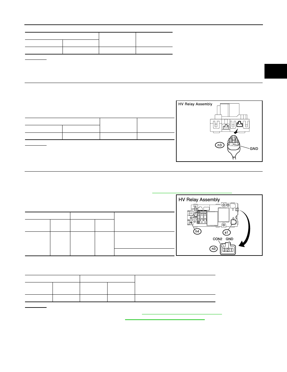
HV Relay Assembly
Ground
Resistance
Harness connector
Terminal
n3
3 (CON2)
Ground
10 k
Ω or higher
HV Relay Assembly
Ground
Resistance
Harness connector
Terminal
n3
2 (GND)
Ground
Below 1
Ω
JMCIA0159GB
HV Relay Assembly
HV Relay Assembly
Resistance
Component
connector
Terminal
Component
connector
Terminal
h4
1
s1
1
Below 1
Ω
[When battery voltage (12 V) ap-
plied to terminals n3-2 and n3-3]
10 k
Ω or higher
HV Relay Assembly
HV Relay Assembly
Resistance
Component
connector
Terminal
Component
connector
Terminal
n3
3 (CON2)
n3
2 (GND)
18.8 to 32.1
Ω at -35 to 80°C (-31 to 176° F)
JMCIA0147GB