Nissan Altima HL32 Hybrid. Manual - part 669
P0AA6-526, P0AA6-611, P0AA6-612, P0AA6-613, P0AA6-614
HBC-425
< COMPONENT DIAGNOSIS >
D
E
F
G
H
I
J
K
L
M
A
B
HBC
N
O
P
OK
>> GO TO 7.
NG
>> Replace hybrid transaxle (See
TM-36, "Removal and Installation"
7.
INSPECT HYBRID TRANSAXLE (MG1)
CAUTION:
Be sure to wear insulated gloves.
1. Check that the service plug grip is not installed.
2. Check the connectors connection.
3. Using a megohmmeter set to 500 V, measure the resistance
according to the value(s) in the table below.
NOTE:
• Be sure to set the megohmmeter to 500 V when perform-
ing this test. Using a setting higher than 500 V can result
in damage to the component being inspected.
OK or NG
OK
>> Replace inverter with converter assembly (See
HBC-638, "Removal and Installation"
).
NG
>> Replace hybrid transaxle (See
TM-36, "Removal and Installation"
8.
CHECK AIR CONDITIONING HARNESS ASSEMBLY
CAUTION:
Be sure to wear insulated gloves.
1. Turn ignition switch OFF and remove the service plug grip (See
HBC-632, "Precautions for Inspecting the
NOTE:
After removing the service plug grip, do not turn ignition switch ON (READY), unless instructed by the ser-
vice manual because this may cause a malfunction.
2. Disconnect the air conditioning harness assembly from the elec-
tric compressor.
-
Green lock (1)
Dirt or foreign objects have not entered the connection, or there is no evidence
of contamination.
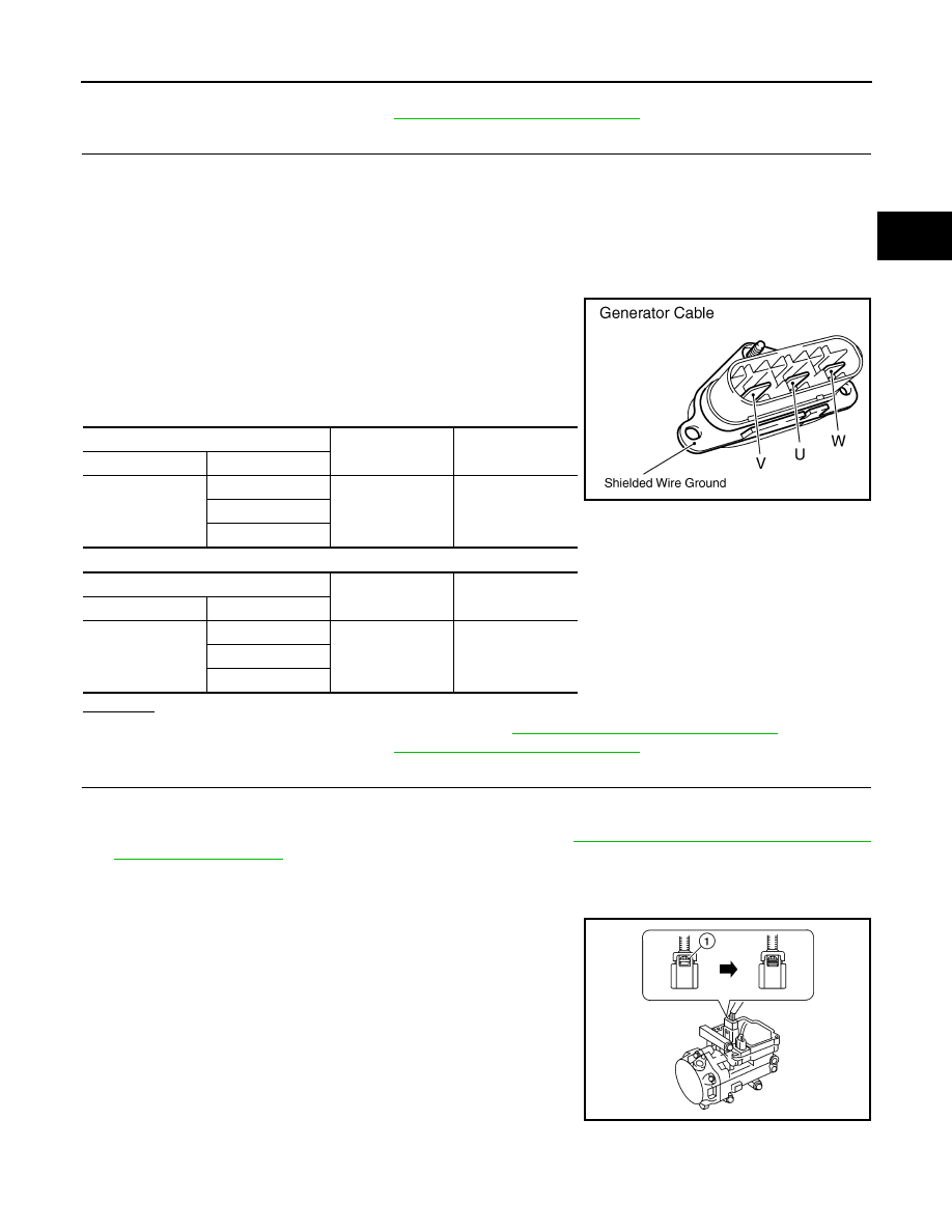
Generator Cable
Ground
Resistance
Harness connector
Terminal
—
U
Ground
20 M
Ω or higher
V
W
Generator Cable
Shielded wire
ground
Resistance
Harness connector
Terminal
—
U
Shielded wire
ground
20 M
Ω or higher
V
W
JMCIA0137GB
ALCIA0109ZZ