Nissan Altima HL32 Hybrid. Manual - part 568
HYBRID CONTROL SYSTEM
HBC-21
< FUNCTION DIAGNOSIS >
D
E
F
G
H
I
J
K
L
M
A
B
HBC
N
O
P
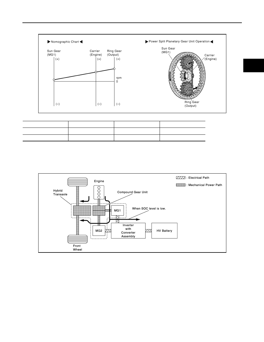
• The following nomographic charts and the illustrations of the power split planetary gear unit operation for
each vehicle driving condition represent one situation as an example.
Condition of power split planetary gear unit
(D): During Low Load and Constant-Speed Cruising
• When the vehicle is driving under low load and constant-speed cruising conditions, the motive force of the
engine is transmitted by the planetary gears. Some of this motive force is output directly, and the remaining
motive force is used for generating electricity through MG1. Through the use of the electrical path of an
inverter, this electrical power is transmitted to MG2 to be output as the motive force of MG2.
If the SOC level of the HV battery is low, it is charged by MG1 driven by the engine.
• The following represents an example of the power split planetary gear unit operation under normal driving
conditions. The sun gear, carrier and ring gear rotate in the (+) direction. The torque from the engine acts on
the carrier (Engine) in the (+) direction, causing the sun gear and ring gear to react in the (-) direction.
MG1 generates electricity by harnessing the (-) torque that acts on the sun gear.
JMCIA0042GB
Sun Gear (MG1)
Carrier (Engine)
Ring Gear (Output)
Rotational Direction
+
+
+
Torque Condition
+
-
+
JMCIA0046GB