Nissan Altima HL32 Hybrid. Manual - part 520
 

  Index      Nissan     Nissan Altima HL32 Hybrid (2009 year) - Service and Repair Manual


Search            


Content   ..  518  519  520  521   ..


Nissan Altima HL32 Hybrid. Manual - part 520


ECM

HAC-101

< ECU DIAGNOSIS >

[AUTOMATIC AIR CONDITIONER]

C

D

E

F

G

H

J

K

L

M

A

B

HAC

N

O

P

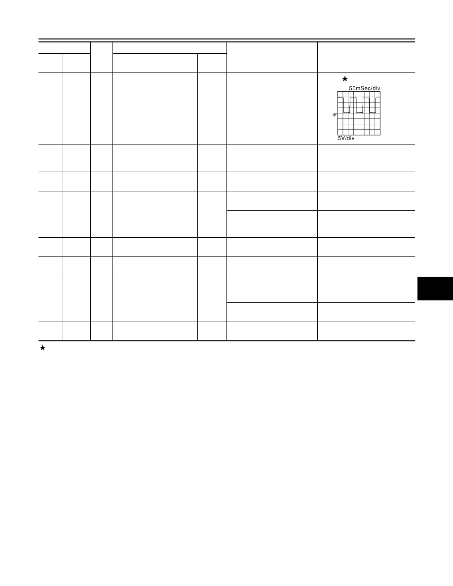
: Average voltage for pulse signal (Actual pulse signal can be confirmed by oscilloscope.)

103

Ground

L

Engine TDC signal output

Output

[Engine is running]
• Warm-up condition
• Idle speed

NOTE:
The pulse cycle changes de-
pending on rpm at idle

0 - 14V

104

Ground

B/W

Sensor ground
(Fuel tank temperature sen-
sor)

[Engine is running]
• Warm-up condition
• Idle speed

0V

105

Ground

R/G

Power supply for ECM

Input

[Ignition switch: ON]

BATTERY VOLTAGE
(11 - 14V)

106

Ground

SB

Stop lamp switch

Input

[Ignition switch: OFF]
• Brake pedal: Fully released

0V

[Ignition switch: OFF]
• Brake pedal: Slightly de-

pressed

BATTERY VOLTAGE
(11 - 14V)

107
108

Ground

B
B

ECM ground

[Engine is running]
• Idle speed

Body ground

109

Ground

LG

EVAP canister vent control 
valve

Output

[Ignition switch: ON]

BATTERY VOLTAGE
(11 - 14V)

110

Ground

G/B

ASCD brake switch

Input

[Ignition switch: ON]
• Brake pedal: Slightly de-

pressed

0V

[Ignition switch: ON]
• Brake pedal: Fully released

BATTERY VOLTAGE
(11 - 14V)

111

112

Ground

B
B

ECM ground

[Engine is running]
• Idle speed

Body ground

Terminal No.

Wire 

color

Description

Condition

Value

(Approx.)

+

-–

Signal name

Input/

Output

JMCIA0008GB

HAC-102

< ECU DIAGNOSIS >

[AUTOMATIC AIR CONDITIONER]

HV ECU

HV ECU

Reference Value

INFOID:0000000004215386

TERMINAL LAYOUT

PHYSICAL VALUES

NOTE:

• The hybrid vehicle control ECU is located behind the passenger side instrument lower panel. For this inspec-

tion, remove passenger side instrument lower panel.

• Specification data are reference values and are measured between each terminal and ground.

• Pulse signal is measured by CONSULT-III.

CAUTION:

Do not use the hybrid vehicle control ECU ground terminals when measuring input/output voltage.

Doing so may result in damage to the hybrid vehicle control ECUs transistor. Use a ground other than

the hybrid vehicle control ECU terminals, such as the ground.

JMCIA0167ZZ

Terminal No.

Wire 

color

Description

Condition

Value

(Approx.)

+

Signal name

Input/

Output

10

Ground

B

hybrid vehicle control 
ECU ground

[Ignition switch: READY]

0V

11

Ground

B

hybrid vehicle control 
ECU ground

[Ignition switch: READY]

0V

12

Ground

B

hybrid vehicle control 
ECU ground

[Ignition switch: READY]

0V

13

Ground

L/R

Generator temperature 
sensor ground

[Ignition switch: READY]

0V

14

Ground

G/R

Generator temperature 
sensor

Input

[Ignition switch: ON]
• Ambient temperature: 25

°C 

(77

°F)

3.4 - 4.9V

[Ignition switch: ON]
• Ambient temperature: 60

°C 

(140

°F)

2.2 - 3.3V

15

Ground

LG/R

Motor temperature sen-
sor ground

[Ignition switch: READY]

0V

16

Ground

BR/R

Motor temperature sen-
sor

Input

[Ignition switch: ON]
• Ambient temperature: 25

°C 

(77

°F)

3.4 - 4.9V

[Ignition switch: ON]
• Ambient temperature: 60

°C 

(140

°F)

2.2 - 3.3V

20

Ground

W

Power supply for hybrid 
vehicle control ECU

Input

[Ignition switch: OFF]

BATTERY VOLTAGE
(11 - 14V)

HV ECU

HAC-103

< ECU DIAGNOSIS >

[AUTOMATIC AIR CONDITIONER]

C

D

E

F

G

H

J

K

L

M

A

B

HAC

N

O

P

37

Ground

R/B

BCM communication
(PNP switch signal)

Output

[Ignition switch: ON]
• Shift position: P or N

BATTERY VOLTAGE
(11 - 14V)

[Ignition switch: ON]
• Shift position: Except above

0 - 1.5V

45

Ground

V

PNP switch
(P position signal)

Input

[Ignition switch: ON]
• Shift position: P

BATTERY VOLTAGE
(11 - 14V)

[Ignition switch: ON]
• Shift position: Except above

0 - 1.5V

46

Ground

Y/B

PNP switch
(R position signal)

Input

[Ignition switch: ON]
• Shift position: R

BATTERY VOLTAGE
(11 - 14V)

[Ignition switch: ON]
• Shift position: Except above

0 - 1.5V

47

Ground

G/B

PNP switch
(N position signal)

Input

[Ignition switch: ON]
• Shift position: N

BATTERY VOLTAGE
(11 - 14V)

[Ignition switch: ON]
• Shift position: Except above

0 - 1.5V

48

Ground

L/B

PNP switch
(D position signal)

Input

[Ignition switch: ON]
• Shift position: D

BATTERY VOLTAGE
(11 - 14V)

[Ignition switch: ON]
• Shift position: Except above

0 - 1.5V

49

Ground

LG/B

PNP switch
(B position signal)

Input

[Ignition switch: ON]
• Shift position: B

BATTERY VOLTAGE
(11 - 14V)

[Ignition switch: ON]
• Engine stopped
• Shift position: Except above

0 - 1.5V

50

Ground

GR/B

PNP switch
(RV position signal)

Input

[Ignition switch: ON]
• Shift position: R

BATTERY VOLTAGE
(11 - 14V)

[Ignition switch: ON]
• Shift position: Except above

0 - 1.5V

51

Ground

P/B

PNP switch
(FD position signal)

Input

[Ignition switch: ON]
• Shift position: D or B

BATTERY VOLTAGE
(11 - 14V)

[Ignition switch: ON]
• Engine stopped
• Shift position: Except above

0 - 1.5V

52

Ground

W/R

PNP switch
(MJ position signal)

Input

[Ignition switch: ON]
• Shift position: P, R, N, D or B

BATTERY VOLTAGE
(11 - 14V)

[Ignition switch: ON]
• Shift position: Except above

0 - 1.5V

Terminal No.

Wire 

color

Description

Condition

Value

(Approx.)

+

Signal name

Input/

Output

HAC-104

< ECU DIAGNOSIS >

[AUTOMATIC AIR CONDITIONER]

HV ECU

53

Ground

R

Compressor inverter 
communication

[Ignition switch: READY]
• A/C system: Not operating

The wave form will vary depend-
ing on the content of the digital 
communication (digital signal).

[Ignition switch: READY]
• A/C system: Operating

The wave form will vary depend-
ing on the content of the digital 
communication (digital signal).

54

Ground

Y

Compressor inverter 
communication

[Ignition switch: READY]
• A/C system: Not operating

The wave form will vary depend-
ing on the content of the digital 
communication (digital signal).

[Ignition switch: READY]
• A/C system: Operating

The wave form will vary depend-
ing on the content of the digital 
communication (digital signal).

55

Ground

L

Compressor inverter 
communication

[Ignition switch: READY]

The wave form will vary depend-
ing on the content of the digital 
communication (digital signal).

Terminal No.

Wire 

color

Description

Condition

Value

(Approx.)

+

Signal name

Input/

Output

JMCIA0001GB

JMCIA0002GB

JMCIA0001GB

JMCIA0002GB

JMCIA0005GB


Content   ..  518  519  520  521   ..