Nissan Altima HL32 Hybrid. Manual - part 304


  Index      Nissan     Nissan Altima HL32 Hybrid (2009 year) - Service and Repair Manual


Search            


Content   ..  302  303  304  305   ..


Nissan Altima HL32 Hybrid. Manual - part 304


EC-200

< COMPONENT DIAGNOSIS >

[QR25DE]

P0138 HO2S2

P0138 HO2S2

Description

INFOID:0000000004362851

The heated oxygen sensor 2, after three way catalyst (manifold),

monitors the oxygen level in the exhaust gas.

Even if switching characteristics of the air fuel ratio (A/F) sensor 1

are shifted, the air-fuel ratio is controlled to stoichiometric, by the sig-

nal from the heated oxygen sensor 2.

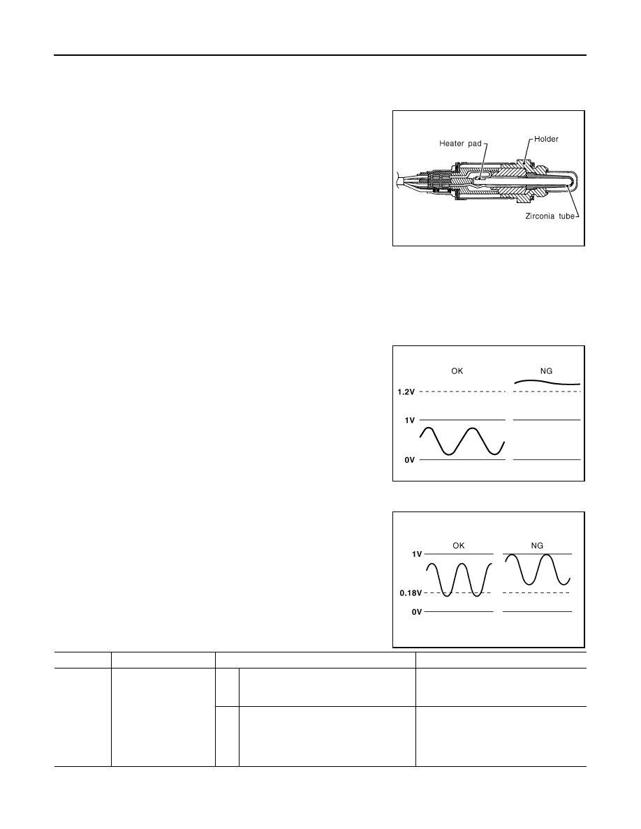
This sensor is made of ceramic zirconia. The zirconia generates volt-

age from approximately 1V in richer conditions to 0V in leaner condi-

tions.

Under normal conditions the heated oxygen sensor 2 is not used for

engine control operation.

DTC Logic

INFOID:0000000004211440

DTC DETECTION LOGIC

The heated oxygen sensor 2 has a much longer switching time between rich and lean than the air fuel ratio (A/

F) sensor 1. The oxygen storage capacity of the three way catalyst (manifold) causes the longer switching

time.

MALFUNCTION A

To judge the malfunctions of heated oxygen sensor 2, ECM monitors

whether the voltage is unusually high during the various driving con-

dition such as fuel-cut.

MALFUNCTION B

To judge the malfunctions of heated oxygen sensor 2, ECM monitors

whether the minimum voltage of sensor is sufficiently low during the

various driving condition such as fuel-cut.

DTC CONFIRMATION PROCEDURE

SEF327R

PBIB1848E

PBIB2376E

DTC No.

Trouble diagnosis name

DTC detecting condition

Possible cause

P0138

Heated oxygen sensor 2 
circuit high voltage

A)

An excessively high voltage from the sen-
sor is sent to ECM.

• Harness or connectors

(The sensor circuit is open or shorted)

• Heated oxygen sensor 2

B)

The minimum voltage from the sensor is 
not reached to the specified voltage.

• Harness or connectors

(The sensor circuit is open or shorted)

• Heated oxygen sensor 2
• Fuel pressure
• Fuel injector

P0138 HO2S2

EC-201

< COMPONENT DIAGNOSIS >

[QR25DE]

C

D

E

F

G

H

I

J

K

L

M

A

EC

N

P

O

1.

PRECONDITIONING

If DTC Confirmation Procedure has been previously conducted, always perform the following before conduct-

ing the next test.

1. Turn ignition switch OFF and wait at least 10 seconds.

2. Turn ignition switch ON.

3. Turn ignition switch OFF and wait at least 10 seconds.

>> GO TO 2.

2.

PERFORM DTC CONFIRMATION PROCEDURE FOR MALFUNCTION A

1. Activate “INSPECTION MODE 1” (

HBC-104

) to start engine, and warm up engine to normal operating

temperature.

2. Turn ignition switch OFF and wait at least 10 seconds.

3. Turn ignition switch ON.

4. Turn ignition switch OFF and wait at least 10 seconds.

5. Turn ignition switch ON (READY).

6. Drive vehicle at a speed of 80 km/h (50 MPH) or more for at least 3 consecutive minutes.

CAUTION:

Always drive vehicle in safe manner according to traffic conditions and obey all traffic laws.

NOTE:

Keep the vehicle speed as steady as possible during the cruising.

7. Check 1st trip DTC.
Is 1st trip DTC detected?

YES

>> Go to 

EC-202, "Diagnosis Procedure"

.

NO-1 >> With CONSULT-III: GO TO 3.

NO-2 >> Without CONSULT-III: GO TO 5.

3.

PERFORM DTC CONFIRMATION PROCEDURE FOR MALFUNCTION B

NOTE:

For better results, perform “DTC WORK SUPPORT” at a temperature of 0 to 30 

°C (32 to 86 °F).

1. Activate “INSPECTION MODE 1” (

HBC-104

) to start engine, and warm up engine to normal operating

temperature.

2. Turn ignition switch OFF and wait at least 10 seconds.

3. Turn ignition switch ON.

4. Turn ignition switch OFF and wait at least 10 seconds.

5. Turn ignition switch ON (READY) and select “DATA MONITOR” mode with CONSULT-III.

6. Drive vehicle at a speed of 80 km/h (50 MPH) or more for at least 3 consecutive minutes.

CAUTION:

Always drive vehicle in safe manner according to traffic conditions and obey all traffic laws.

NOTE:

Keep the vehicle speed as steady as possible during the cruising.

7. Stop the vehicle and shift the selector lever to P position.

8. Fully depress the accelerator pedal and keep it until step 11.

9. Make sure that “COOLAN TEMP/S” indicates more than 70

°C (158°F).

If not, warm up engine and go to next step when “COOLAN TEMP/S” indication reaches to 70

°C (158°F).

10. Select “HO2S2 (B1) P1146” of “HO2S2” in “DTC WORK SUPPORT” mode with CONSULT-III.

11. Touch “START”.

NOTE:

It will take at most 10 minutes until “COMPLETED” is displayed.

12. Touch “SELF-DIAG RESULT”.
Which is displayed on CONSULT-III

OK

>> INSPECTION END

NG

>> Go to 

EC-202, "Diagnosis Procedure"

.

CAN NOT BE DIAGNOSED>>GO TO 4.

4.

PERFORM DTC CONFIRMATION PROCEDURE FOR MALUNCTION B AGAIN

1. Turn ignition switch OFF and leave the vehicle in a cool place (soak the vehicle).

2. Perform DTC CONFIRMATION PROCEDURE again.

EC-202

< COMPONENT DIAGNOSIS >

[QR25DE]

P0138 HO2S2

>> GO TO 3.

5.

PERFORM COMPONENT FUNCTION CHECK FOR MALFUNCTION B

Perform component function check. Refer to 

EC-202, "Diagnosis Procedure"

.

NOTE:

Use component function check to check the overall function of the heated oxygen sensor 2 circuit. During this

check, a 1st trip DTC might not be confirmed.
Is the inspection result normal?

YES

>> INSPECTION END

NO

>> Go to 

EC-202, "Diagnosis Procedure"

.

Component Function Check

INFOID:0000000004211441

1.

PERFORM COMPONENT FUNCTION CHECK

Without CONSULT-III

1. Activate “INSPECTION MODE 1” (

HBC-104

) to start engine, and warm up engine to the normal operating

temperature.

2. Turn ignition switch OFF and wait at least 10 seconds.

3. Turn ignition switch ON.

4. Turn ignition switch OFF and wait at least 10 seconds.

5. Turn ignition ON (READY) and drive vehicle at a speed of 80 km/h (50 MPH) or more for at least 3 con-

secutive minutes.

CAUTION:

Always drive vehicle in safe manner according to traffic conditions and obey all traffic laws.

NOTE:

Keep the vehicle speed as steady as possible during the cruising.

6. Stop vehicle and shift the selector lever to P position.

7. Check the voltage between ECM harness connector and ground

under the following condition.

Is the inspection result normal?

YES

>> INSPECTION END

NO

>> Go to 

EC-202, "Diagnosis Procedure"

.

Diagnosis Procedure

INFOID:0000000004211442

1.

INSPECTION START

Confirm the detected malfunction (A or B). Refer to 

EC-200, "DTC Logic"

.

Which malfunction is detected?

A

>> GO  TO  2.

B

>> GO  TO  9.

2.

CHECK GROUND CONNECTION

1. Turn ignition switch OFF.

2. Check ground connection E9. Refer to Ground Inspection in 

GI-45, "Circuit Inspection"

.

Is the inspection result normal?

YES

>> GO TO 3.

NO

>> Repair or replace ground connection.

3.

CHECK HO2S2 GROUND CIRCUIT FOR OPEN AND SHORT

ECM

Ground

Condition

Voltage

Connector

Terminal

F13

33

(HO2S2 

signal)

Ground

Fully depress the acceler-
ator pedal and keep it, 
then fully release acceler-
ator pedal

The voltage should 
be below 0.18V at 
least once during 
this procedure.

JMBIA1635ZZ

P0138 HO2S2

EC-203

< COMPONENT DIAGNOSIS >

[QR25DE]

C

D

E

F

G

H

I

J

K

L

M

A

EC

N

P

O

1. Disconnect heated oxygen sensor 2 harness connector.

2. Disconnect ECM harness connector.

3. Check the continuity between HO2S2 harness connector and ECM harness connector.

4. Also check harness for short to ground and short to power.
Is the inspection result normal?

YES

>> GO TO 4.

NO

>> Repair open circuit or short to ground or short to power in harness or connectors.

4.

CHECK HO2S2 INPUT SIGNAL CIRCUIT FOR OPEN AND SHORT

1. Check the continuity between HO2S2 harness connector and ECM harness connector.

2. Check the continuity between HO2S2 harness connector or ECM harness connector and ground.

3. Also check harness for short to power.
Is the inspection result normal?

YES

>> GO TO 5.

NO

>> Repair open circuit or short to ground or short to power in harness or connectors.

5.

CHECK HO2S2 CONNECTOR FOR WATER

Check connectors for water.

Is the inspection result normal?

YES

>> GO TO 6.

NO

>> Repair or replace harness or connectors.

6.

CHECK HEATED OXYGEN SENSOR 2

Refer to 

EC-205, "Component Inspection"

.

Is the inspection result normal?

YES

>> GO TO 8.

NO

>> GO TO 7.

7.

REPLACE HEATED OXYGEN SENSOR 2

Replace heated oxygen sensor 2.

CAUTION:

• Discard any sensor which has been dropped from a height of more than 0.5 m (19.7 in) onto a hard

surface such as a concrete floor; use a new one.

• Before installing new sensor, clean exhaust system threads using oxygen sensor thread cleaner

[commercial service tool: (J-43897-18 or J-43897-12)] and approved anti-seize lubricant (commercial

service tool).

>> INSPECTION END

8.

CHECK INTERMITTENT INCIDENT

HO2S2

ECM

Continuity

Connector Terminal Connector Terminal

F42

1

F13

35

Existed

HO2S2

ECM

Continuity

Connector Terminal Connector Terminal

F42

4

F13

33

Existed

HO2S2

ECM

Ground

Continuity

Connector Terminal Connector Terminal

F42

4

F13

33

Ground Not existed

Water should not exist.


Content   ..  302  303  304  305   ..