Nissan Altima HL32 Hybrid. Manual - part 102
BRAKE PEDAL
BR-19
< ON-VEHICLE REPAIR >
C
D
E
G
H
I
J
K
L
M
A
B
BR
N
O
P
ON-VEHICLE REPAIR
BRAKE PEDAL
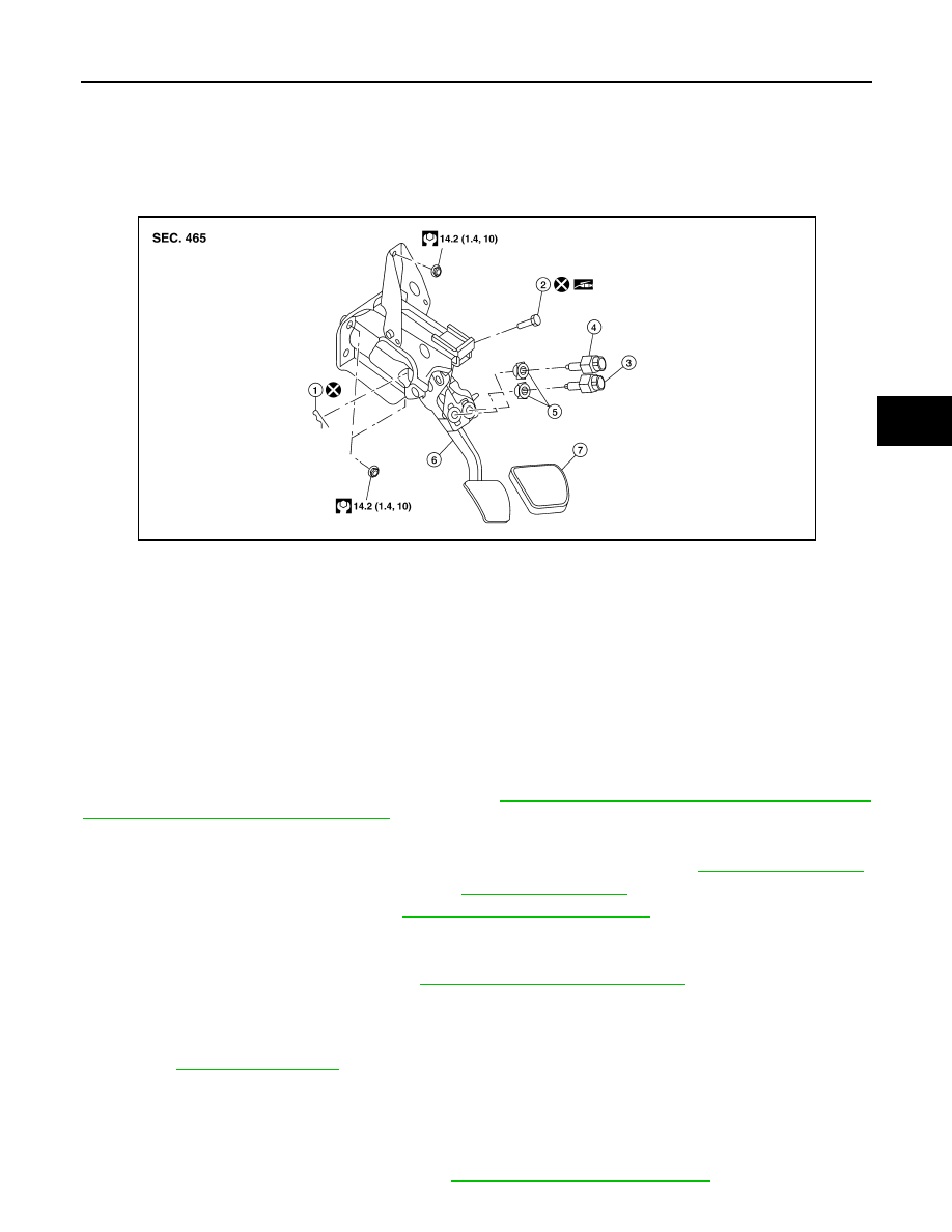
Exploded View
INFOID:0000000004496020
NOTE:
The clevis pin must be installed from the right side as shown above.
Removal and Installation
INFOID:0000000004496021
CAUTION:
When the brake pedal position moves after the replacement of stop lamp switch, the replacement of
brake pedal or brake pedal height adjustment, measure the zero-point voltage of the brake stroke sen-
sor and confirm that the value is within the normal range. If the value is out of normal range, perform
the adjustment of the brake stroke sensor. Refer to
BRC-9, "PERFORM ADJUSTMENT OF STROKE
SENSOR : Special Repair Requirement"
REMOVAL
1. Remove the instrument lower cover (LH) and lower knee protector (LH). Refer to
2. Remove the console side finisher (LH). Refer to
3. Remove the accelerator pedal. Refer to
ACC-3, "Removal and Installation"
.
4. Disconnect the stop lamp switch and ASCD cancel switch connector.
5. Remove the stop lamp switch and ASCD cancel switch from the brake pedal assembly.
6. Remove the brake stroke sensor. Refer to
BRC-209, "Removal and Installation"
.
7. Remove the snap pin and clevis pin to disconnect the brake booster clevis from the brake pedal assembly.
8. Remove the brake booster clevis from the input rod.
9. Disconnect the steering column assembly pinch bolt to position the steering column assembly aside.
10. Remove the six brake pedal assembly nuts.
11. Remove the brake pedal assembly from vehicle.
INSTALLATION
Installation is in the reverse order of removal.
• Tightening torque for the lock nut is referred to in
BR-12, "Inspection and Adjustment"
1.
Snap pin
2.
Clevis pin
3.
Stop lamp switch
4.
ASCD cancel switch
5.
Clip
6.
Brake pedal assembly
7.
Brake pedal pad
AWFIA0331GB