Nissan Sentra. Manual - part 897


  Index      Nissan     Nissan Sentra (2014 year) - Service and Repair Manual


Search            


Content   ..  895  896  897  898   ..


Nissan Sentra. Manual - part 897


TM-224

< DTC/CIRCUIT DIAGNOSIS >

[CVT: RE0F11A]

P2765 INPUT SPEED SENSOR B

Is the inspection result normal?

YES 

>> GO TO 2.

NO

>> GO TO 6.

2.

CHECK SECONDARY SPEED SENSOR GROUND CIRCUIT 

Check continuity between of secondary speed sensor harness connector terminal and ground. 

Is the inspection result normal?

YES 

>> GO TO 3.

NO

>> Repair or replace malfunctioning parts.

3.

CHECK CIRCUIT BETWEEN SECONDARY SPEED SENSOR AND TCM (PART 1)

1. Turn ignition switch OFF.

2. Disconnect TCM connector.

3. Check continuity between secondary speed sensor harness connector terminal and TCM harness con-

nector terminal.

Is the inspection result normal?

YES 

>> GO TO 4.

NO

>> Repair or replace malfunctioning parts.

4.

CHECK CIRCUIT BETWEEN SECONDARY SPEED SENSOR AND TCM (PART 2)

Check continuity between secondary speed sensor harness connector terminal and ground. 

Is the inspection result normal?

YES 

>> GO TO 5.

NO

>> Repair or replace malfunctioning parts.

5.

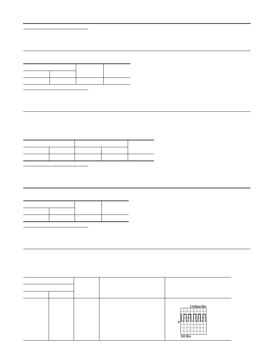
CHECK TCM INPUT SIGNALS

1. Connect all of disconnected connectors.

2. Lift the vehicle.

3. Start the engine.

4. Check frequency of secondary speed sensor.

Secondary speed sensor

Continuity

Connector

Terminal

F30

1

Ground

Existed

Secondary speed sensor

TCM

Continuity

Connector

Terminal

Connector

Terminal

F30

2

F23

34

Existed

Secondary speed sensor

Continuity

Connector

Terminal

F30

2

Ground

Not existed

+

-

Condition

Frequency

(Approx.)

TCM

Connector

Terminal

F23

34

Ground

• Selector lever: “L” position
• Vehicle speed: 20 km/h (12 MPH)

700 Hz

JSDIA1905GB

P2765 INPUT SPEED SENSOR B

TM-225

< DTC/CIRCUIT DIAGNOSIS >

[CVT: RE0F11A]

C

E

F

G

H

I

J

K

L

M

A

B

TM

N

O

P

Is the inspection result normal?

YES 

>> Check intermittent incident. Refer to 

GI-39, "Intermittent Incident"

.

NO

>> Replace secondary speed sensor

TM-269, "Removal and Installation"

.

6.

DETECT MALFUNCTIONING ITEMS

Check the following items:

• Harness open circuit or short circuit between ignition switch and IPDM E/R. Refer to 

PG-20, "Wiring Diagram

— Ignition Power Supply —"

.

• Harness open circuit or short circuit between IPDM E/R and secondary speed sensor.

• 10A fuse (No.45, IPDM E/R). Refer to 

PG-49, "IPDM E/R Terminal Arrangement"

.

• IPDM E/R
Is the check result normal?

YES

>> Check intermittent incident. Refer to 

GI-39, "Intermittent Incident"

.

NO

>> Repair or replace malfunctioning parts.

TM-226

< DTC/CIRCUIT DIAGNOSIS >

[CVT: RE0F11A]

P2857 CLUTCH A PRESSURE

P2857 CLUTCH A PRESSURE

DTC Logic

INFOID:0000000009759474

DTC DETECTION LOGIC

DTC CONFIRMATION PROCEDURE

CAUTION:

• Be sure to perform 

TM-226, "Diagnosis Procedure"

” and then perform “DTC CONFIRMATION PRO-

CEDURE”.

• Never perform “DTC CONFIRMATION PROCEDURE” before the repairs. Doing so may result in a sec-

ondary malfunction.

• Be careful of the driving speed.

1.

PREPARATION BEFORE WORK

If another “DTC CONFIRMATION PROCEDURE” occurs just before, turn ignition switch OFF and wait for at

least 10 seconds, then perform the next test.

>> GO TO 2.

2.

CHECK DTC DETECTION

1. Start the engine.

2. Drive the vehicle.

3. Maintain the following conditions for 10 seconds or more.

4. Stop the vehicle.

5. Check the first trip DTC.
Is “P2857” detected?

YES

>> Go to 

TM-226, "Diagnosis Procedure"

.

NO

>> INSPECTION END

Diagnosis Procedure

INFOID:0000000009759475

1.

CHECK INTERMITTENT INCIDENT

Refer to 

GI-39, "Intermittent Incident"

Is the inspection result normal?

YES 

>> Replace the transaxle assembly. Refer to 

TM-283, "Removal and Installation"

.

DTC

CONSULT screen terms

(Trouble diagnosis content)

DTC detection condition

Possible causes

P2857

CLUTCH A PRESSURE
(Clutch A Pressure Engage-
ment Performance)

The auxiliary gearbox gear ratio is 2.232 or 
more for the auxiliary gearbox 1GR ratio con-
tinuously for 5 seconds or more under the fol-
lowing diagnosis conditions:
• Diagnosis conditions
- Selector lever: Other than “P”, “R” and “N” 

positions

- Accelerator pedal position: 0.7/8 or more
- Engine speed: More than 550 rpm
- Output speed: More than 300 rpm
- Secondary pulley speed: More than 300 

rpm

- Command for the 1GR of auxiliary gearbox 

is in progress.

- Auxiliary gearbox shifting is not in progress. 
- TCM power supply voltage: More than 11 V

• Low brake solenoid valve
• Control valve assembly

Selector lever

: “L” POSITION

Accelerator pedal position

: 0.7/8 or more

Vehicle speed

: 10 km/h (6 MPH) or more

P2857 CLUTCH A PRESSURE

TM-227

< DTC/CIRCUIT DIAGNOSIS >

[CVT: RE0F11A]

C

E

F

G

H

I

J

K

L

M

A

B

TM

N

O

P

NO

>> Repair or replace malfunctioning parts.


Content   ..  895  896  897  898   ..