Nissan Sentra. Manual - part 441


  Index      Nissan     Nissan Sentra (2014 year) - Service and Repair Manual


Search            


Content   ..  439  440  441  442   ..


Nissan Sentra. Manual - part 441


EC-460

< DTC/CIRCUIT DIAGNOSIS >

[MRA8DE]

IGNITION SIGNAL

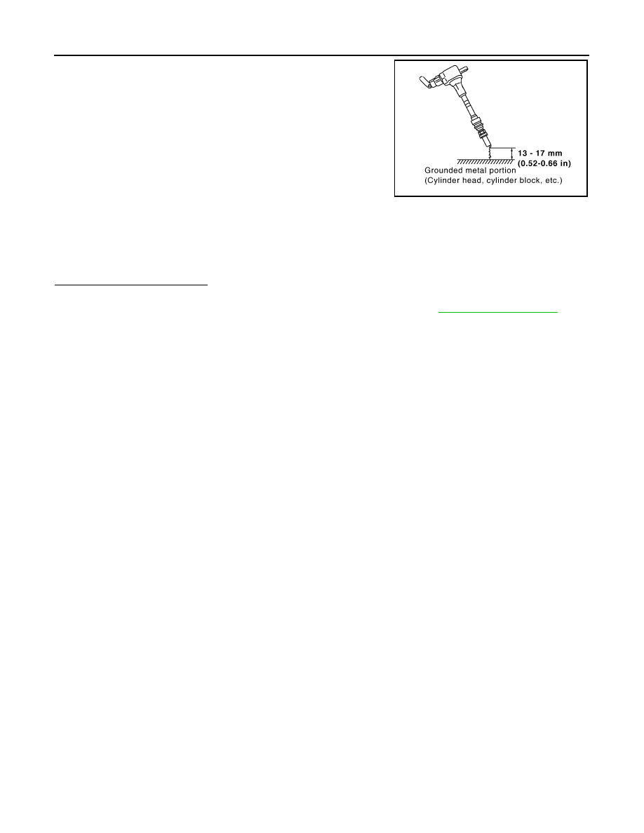
11. Fix ignition coil using a rope etc. with gap of 13 - 17 mm (0.52 -

0.66 in) between the edge of the spark plug and grounded metal

portion as shown in the figure.

12. Crank engine for about three seconds, and check whether spark

is generated between the spark plug and the grounded metal

portion.

CAUTION:

• During the operation, always stay 0.5 cm (19.7 in) away

from the spark plug and the ignition coil. Be careful not to

get an electrical shock while checking, because the elec-

trical discharge voltage becomes 20 kV or more.

• It might cause to damage the ignition coil if the gap of more than 17 mm (0.66 in) is taken.

NOTE:

When the gap is less than 13 mm (0.52 in), the spark might be generated even if the coil is mal-

functioning.

Is the inspection result normal?

YES

>> INSPECTION END

NO

>> Replace malfunctioning ignition coil with power transistor. Refer to 

EM-45, "Exploded View"

.

Spark should be generated.

JMBIA0066GB

ELECTRICAL LOAD SIGNAL

EC-461

< DTC/CIRCUIT DIAGNOSIS >

[MRA8DE]

C

D

E

F

G

H

I

J

K

L

M

A

EC

N

P

O

ELECTRICAL LOAD SIGNAL

Description

INFOID:0000000009758718

The electrical load signal (Headlamp switch signal, rear window defogger switch signal, etc.) is transferred via

the CAN communication line.

Component Function Check

INFOID:0000000009758719

1.

CHECK REAR WINDOW DEFOGGER SWITCH FUNCTION

With CONSULT

1. Turn ignition switch ON.

2. Select “DATA MONITOR” mode of “ENGINE” using CONSULT.

3. Select “LOAD SIGNAL” and check indication as per the following conditions.

Is the inspection result normal?

YES

>> GO TO 2.

NO

>> Proceed to 

EC-461, "Diagnosis Procedure"

.

2.

CHECK LIGHTING SWITCH FUNCTION

With CONSULT

Check “LOAD SIGNAL” indication as per the following conditions.

Is the inspection result normal?

YES

>> GO TO 3.

NO

>> Proceed to 

EC-461, "Diagnosis Procedure"

.

3.

CHECK HEATER FAN CONTROL SWITCH FUNCTION

With CONSULT

Select “HEATER FAN SW” and check indication as per the following conditions.

Is the inspection result normal?

YES

>> INSPECTION END

NO

>> Proceed to 

EC-461, "Diagnosis Procedure"

.

Diagnosis Procedure

INFOID:0000000009758720

1.

INSPECTION START

Confirm the malfunctioning circuit (rear window defogger, headlamp or heater fan). Refer to 

EC-461, "Compo-

nent Function Check"

.

Which circuit is related to the incident?

Rear window defogger>>GO TO 2.

Headlamp>>GO TO 3.

Heater fan>>GO TO 4.

Monitor item

Condition

Indication

LOAD SIGNAL

Rear window defogger switch

ON

ON

OFF

OFF

Monitor item

Condition

Indication

LOAD SIGNAL

Lighting switch

ON at 2nd posi-
tion

ON

OFF

OFF

Monitor item

Condition

Indication

HEATER FAN 
SW

Heater fan control switch

ON

ON

OFF

OFF

EC-462

< DTC/CIRCUIT DIAGNOSIS >

[MRA8DE]

ELECTRICAL LOAD SIGNAL

2.

CHECK REAR WINDOW DEFOGGER SYSTEM

Check the rear window defogger system. Refer to 

DEF-27, "Work Flow"

.

>> INSPECTION END

3.

CHECK HEADLAMP SYSTEM

Check the headlamp system. Refer to 

EXL-85, "Work Flow"

.

>> INSPECTION END

4.

CHECK HEATER FAN CONTROL SYSTEM

Check the heater fan control system. Refer to 

HA-15, "Workflow"

.

>> INSPECTION END

COOLING FAN

EC-463

< DTC/CIRCUIT DIAGNOSIS >

[MRA8DE]

C

D

E

F

G

H

I

J

K

L

M

A

EC

N

P

O

COOLING FAN

Component Function Check

INFOID:0000000009758721

1.

CHECK COOLING FAN FUNCTION

With CONSULT

1. Turn ignition switch ON.

2. Perform “FAN” in “ACTIVE TEST” mode of “ENGINE” using CONSULT.

3. Check that cooling fan operates at low speed or high speed.

Without CONSULT

1. Activate IPDM E/R auto active test and check cooling fan motors operation. Refer to 

PCS-9, "Diagnosis

Description"

 (with intelligent key), or 

PCS-37, "Diagnosis Description"

 (without intelligent key).

2. Check that cooling fan operates.
Is the inspection result normal?

YES

>> INSPECTION END

NO

>> Proceed to 

EC-463, "Diagnosis Procedure"

.

Diagnosis Procedure

INFOID:0000000009758722

1.

CHECK COOLING FAN MOTOR GROUND CIRCUIT

1. Turn ignition switch OFF.

2. Disconnect cooling fan motor harness connector.

3. Check the continuity between cooling fan motor harness connector and ground.

4. Also check harness for short to ground.
Is the inspection result normal?

YES

>> GO TO 2.

NO

>> Repair or replace error-detected parts.

2.

CHECK COOLING FAN MOTOR CIRCUIT-1

1. Disconnect IPDM E/R harness connector.

2. Check the continuity between IPDM E/R harness connector and cooling fan motor harness connector.

3. Also check harness for short to ground.
Is the inspection result normal?

YES

>> GO TO 3.

NO

>> Repair or replace error-detected parts.

3.

CHECK COOLING FAN MOTOR

Check cooling fan motor. Refer to 

EC-464, "Component Inspection (Cooling Fan Motor)"

.

Is the inspection result normal?

YES

>> GO TO 4.

NO

>> Replace cooling fan motor. Refer to 

CO-17, "Removal and Installation"

.

+

Continuity

Cooling fan motor

Connector

Terminal

E53

3

Ground

Existed

+

Continuity

IPDM E/R

Cooling fan motor

Connector

Terminal

Connector

Terminal

E44

23

E53

1

Existed

21

2

E48

58

4


Content   ..  439  440  441  442   ..