Nissan Leaf. Manual - part 682
FRONT WHEEL HUB AND KNUCKLE
FAX-9
< REMOVAL AND INSTALLATION >
C
E
F
G
H
I
J
K
L
M
A
B
FAX
N
O
P
REMOVAL AND INSTALLATION
FRONT WHEEL HUB AND KNUCKLE
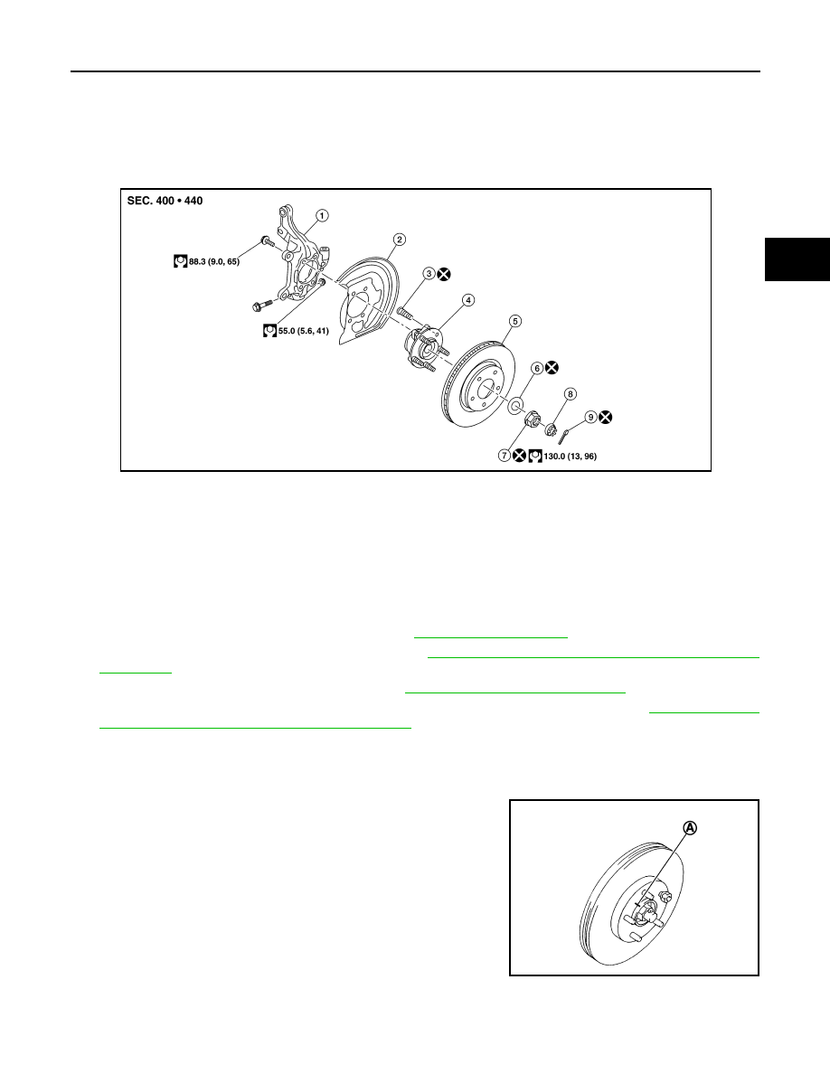
Exploded View
INFOID:0000000010121659
Removal and Installation
INFOID:0000000010121660
REMOVAL
1. Remove wheel and tire using power tool. Refer to
2. Remove wheel sensor and sensor harness. Refer to
BRC-158, "FRONT WHEEL SENSOR : Removal and
.
3. Remove lock plate from strut assembly. Refer to
BR-503, "FRONT : Exploded View"
.
4. Remove caliper assembly. Hang caliper assembly not to interfere with work. Refer to
CALIPER ASSEMBLY : Removal and Installation"
.
CAUTION:
Do not depress brake pedal while brake caliper is removed.
5. Remove disc rotor.
CAUTION:
• Put matching marks (A) on the wheel hub assembly and
the disc rotor before removing the disc rotor.
• Do not drop disc rotor.
1.
Steering knuckle
2.
Splash guard
3.
Hub bolt
4.
Wheel hub assembly (Bearing-inte-
grated type)
5.
Disc rotor
6.
Washer
7.
Wheel hub lock nut
8.
Nut retainer
9.
Cotter pin
AWDIA1171ZZ
JPDIG0066ZZ