Nissan Leaf. Manual - part 604


  Index      Nissan     Nissan Leaf (2011-2014 year) - Service and Repair Manual


Search            


Content   ..  602  603  604  605   ..


Nissan Leaf. Manual - part 604


SYSTEM

EXL-17

< SYSTEM DESCRIPTION >

[LED HEADLAMP]

C

D

E

F

G

H

I

J

K

M

A

B

EXL

N

O

P

AUTO LIGHT SYSTEM (FOR CANADA)
AUTO LIGHT SYSTEM (FOR CANADA) : System Description

INFOID:0000000010121321
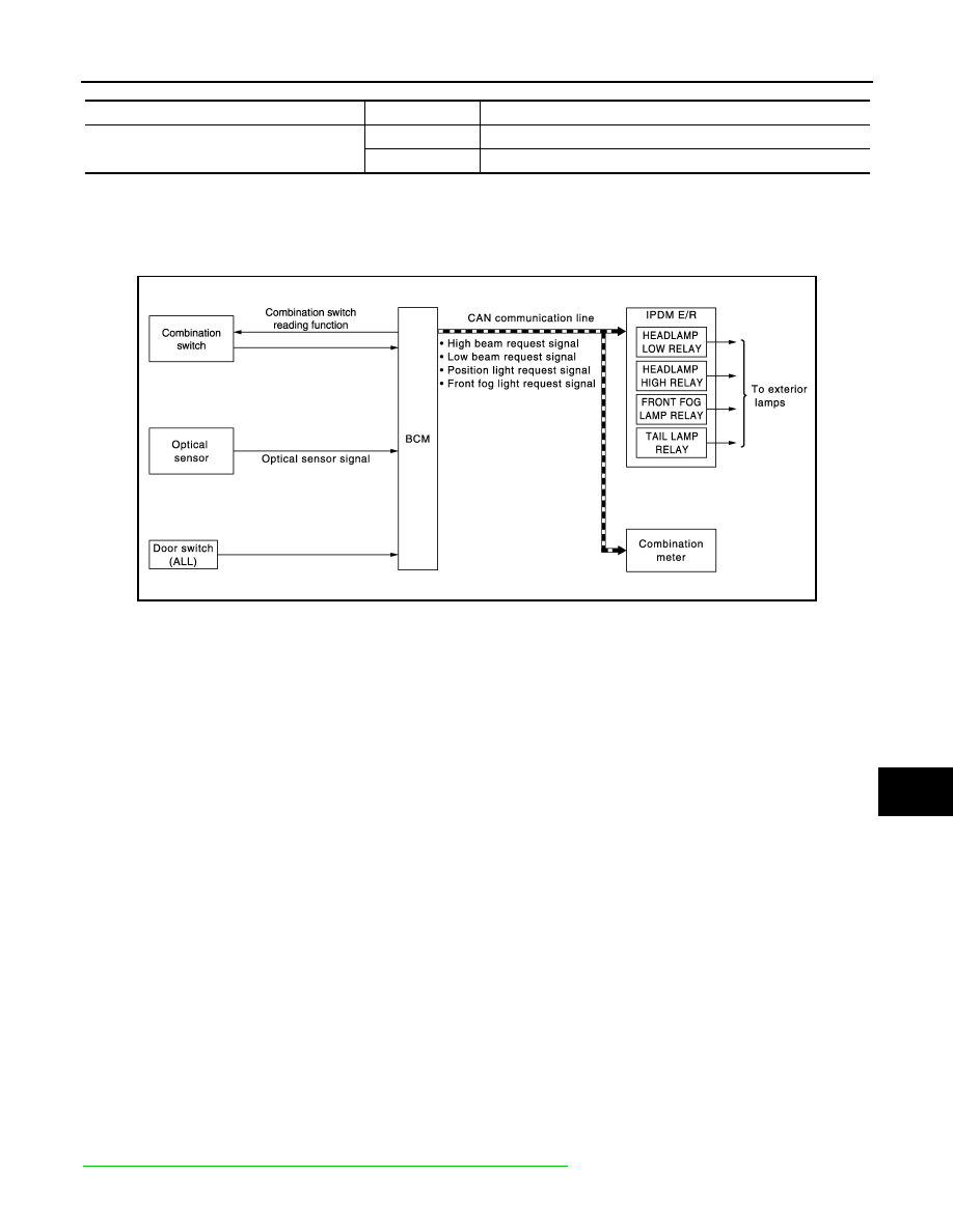
SYSTEM DIAGRAM

OUTLINE

•  Auto light system is controlled by each function of BCM and IPDM E/R.

Control by BCM:

- Combination switch reading function

- Headlamp control function

- Auto light function

- Delay timer function

- Auto light adjustment system

Control by IPDM E/R:

- Relay control function

• Auto light system has the auto light function and delay timer function.

- Auto light function automatically turns ON/OFF the exterior lamps* and each illumination automatically,

depending on the outside brightness.

- When auto light system turns the exterior lamps ON with the power switch OFF, delay timer function turns

the exterior lamps OFF, depending on the vehicle condition with the auto light function after a certain period

of time.

*: Headlamp (LO/HI), parking lamp, side marker lamp, tail lamp and front fog lamp (Headlamp HI and front fog

lamp depend on the combination switch condition.)

AUTO LIGHT FUNCTION

• BCM detects the combination switch condition with the combination switch reading function.

• BCM supplies voltage to optical sensor when the power switch is turned ON or ACC.

• Optical sensor converts outside brightness (lux) to voltage and transmits the optical sensor signal to BCM.

• BCM judges outside brightness from the optical sensor signal and judges ON/OFF condition of the exterior

lamp and each illumination according to the outside brightness. 

• BCM transmits each request signal to IPDM E/R and combination meter via CAN communication according

to ON/OFF condition by the auto light function.

NOTE:

ON/OFF timing differs based on the sensitivity from the setting. The setting can be set by CONSULT. Refer to

BCS-17, "HEADLAMP : CONSULT Function (BCM - HEAD LAMP)"

.

Service item

Setting item

Setting

FOG LAMP OVERRIDE

On

With fog override function

Off

Without fog override function

JMLIA1254GB

EXL-18

< SYSTEM DESCRIPTION >

[LED HEADLAMP]

SYSTEM

AUTO LIGHT ADJUSTMENT SYSTEM

The auto light adjustment system automatically, dims/brightens the display, according to brightness outside

the vehicle, when lighting switch 1ST, lighting switch 2ND or lighting switch AUTO is operated. Refer to 

INL-

12, "AUTO LIGHT ADJUSTMENT SYSTEM : System Description"

.

DELAY TIMER FUNCTION

BCM turns the exterior lamp OFF depending on the vehicle condition with the auto light function when the

power switch is turned OFF.

• Turns the exterior lamp OFF 5 minutes after detecting that any door opens. (Door switch ON).

• Turns the exterior lamp OFF a certain period of time* after closing all doors. (Door switch ON

→OFF).

• Turns the exterior lamp OFF with the power switch ACC or the light switch OFF.

*: The preset time is 45 seconds. The timer operating time can be set by CONSULT. Refer to 

BCS-17, "HEAD-

LAMP : CONSULT Function (BCM - HEAD LAMP)"

.

NOTE:

When any position other than the light switch AUTO is set, the auto light system function switches to the exte-

rior lamp battery saver function.

FOG OVERRIDE FUNCTION

When front fog lamp switch is ON while power switch is in ON position and lighting switch is in AUTO position,

BCM turns ON exterior lamps* regardless of outside brightness.

*: Headlamp (LO/HI), front fog lamp, parking lamp, license plate lamp, side marker lamp and tail lamp.

NOTE:

• Headlamp (HI) depending on the combination switch condition.

• Front fog light reminder warning is cancelled when fog override function is Off.

How to Set

With CONSULT

1. Turn power switch ON.

2. Select “INT LAMP” of “BCM” using CONSULT.

3. Select “FOG LAMP OVERRIDE” in “Work Support” mode.

DAYTIME RUNNING LIGHT SYSTEM
DAYTIME RUNNING LIGHT SYSTEM : System Description

INFOID:0000000010121323

SYSTEM DIAGRAM

OUTLINE

• Turns the headlamp high ON (high beam at approximately half illumination) as the daytime running light.

• Daytime running light is controlled by daytime running light control function and combination switch reading

function of BCM, and relay control function of IPDM E/R.

Service item

Setting item

Setting

FOG LAMP OVERRIDE

On

With fog override function

Off

Without fog override function

JMLIA2416GB

SYSTEM

EXL-19

< SYSTEM DESCRIPTION >

[LED HEADLAMP]

C

D

E

F

G

H

I

J

K

M

A

B

EXL

N

O

P

DAYTIME RUNNING LIGHT OPERATION 

• BCM detects the combination switch condition by the combination switch reading function.

• BCM detects the vehicle condition according to power switch

• BCM detects the parking brake condition by the parking brake switch signal received from combination

meter using CAN communication.

• BCM transmits the daytime running light request signal to IPDM E/R using CAN communication according to

the daytime running light ON condition.

Daytime running light ON condition:

- Vehicle condition READY

- Lighting switch OFF or 1ST

- Lighting switch AUTO, and the auto light function OFF judgment

- Parking brake switch OFF

• IPDM E/R controls the daytime running light relay (ground-side) to turn ON according to the daytime running

light request signal.

• Power is supplied from the daytime running light relay through headlamp high RH and IPDM E/R to head-

lamp high LH. And high beam headlamps are illuminated (approximately half illumination) as the daytime

running light.

TURN SIGNAL AND HAZARD WARNING LAMP SYSTEM
TURN SIGNAL AND HAZARD WARNING LAMP SYSTEM : System Description

INFOID:0000000010121324

SYSTEM DIAGRAM

OUTLINE

Turn signal lamp and the hazard warning lamp is controlled by combination switch reading function and the

flasher control function of BCM.

TURN SIGNAL LAMP OPERATION

• BCM detects the combination switch condition by the combination switch reading function.

• BCM supplies voltage to the right (left) turn signal lamp circuit when the power switch is ON and the turn sig-

nal switch is in the right (left) position. BCM blinks the turn signal lamp.

HAZARD WARNING LAMP OPERATION

BCM supplies voltage to both turn signal lamp circuit when the hazard switch is ON. BCM blinks the hazard

warning lamp.

TURN SIGNAL INDICATOR LAMP AND TURN SIGNAL OPERATION

• BCM transmits the turn signal indicator lamp signal to the combination meter using CAN communication

while the turn signal lamp and the hazard warning lamp are operating.

• Combination meter outputs the turn signal sound with the integrated buzzer while blinking the turn signal

indicator lamp according to the turn signal indicator lamp signal.

3-TIME FLASH FUNCTION

• By a short touch of the turn signal lever, BCM blinks the turn signal 3 times in the selected direction. 

ALLIA1448GB

EXL-20

< SYSTEM DESCRIPTION >

[LED HEADLAMP]

SYSTEM

• Cancels the operation when short touch of the turn signal lever in the reverse direction during the 3_time

flasher function operation.

HIGH FLASHER OPERATION

• BCM detects the turn signal lamp circuit status from the current value.

• BCM increases the turn signal lamp blinking speed if the bulb or harness open is detected with the turn sig-

nal lamp operating.

NOTE:

The blinking speed is normal while operating the hazard warning lamp.

PARKING, LICENSE PLATE, SIDE MARKER AND TAIL LAMP SYSTEM
PARKING, LICENSE PLATE, SIDE MARKER AND TAIL LAMP SYSTEM : System De-
scription

INFOID:0000000010121325

SYSTEM DIAGRAM

OUTLINE

Parking, license plate, side marker and tail lamps are controlled by combination switch reading function and

headlamp control function of BCM, and relay control function of IPDM E/R.

PARKING, LICENSE PLATE, SIDE MARKER AND TAIL LAMPS OPERATION 

• BCM detects the combination switch condition by the combination switch reading function.

• BCM transmits the position light request signal to IPDM E/R and the combination meter via CAN communi-

cation according to the ON/OFF condition of the parking, license plate, side marker and tail lamps.

Parking, license plate, side marker and tail lamps ON condition:

- Lighting switch 1ST

- Lighting switch 2ND

- Lighting switch AUTO, and the auto light function ON judgment

- Lighting switch AUTO, with the front fog lamp switch ON and the power switch ON

• IPDM E/R turns the integrated tail lamp relay ON and turns the parking, license plate, side marker and tail

lamps ON according to the position light request signal.

• Combination meter turns the tail lamp indicator lamp ON according to the position light request signal.

PARKING, LICENSE PLATE, SIDE MARKER AND TAIL LAMP SYSTEM : Fail-Safe

INFOID:0000000010121326

CAN COMMUNICATION CONTROL

When CAN communication with BCM is impossible, IPDM E/R performs fail-safe control. After CAN communi-

cation recovers normally, it also returns to normal control.

If No CAN Communication Is Available With BCM

JMLIA1818GB


Content   ..  602  603  604  605   ..