Nissan Leaf. Manual - part 586


  Index      Nissan     Nissan Leaf (2011-2014 year) - Service and Repair Manual


Search            


Content   ..  584  585  586  587   ..


Nissan Leaf. Manual - part 586


EVC-368

< DTC/CIRCUIT DIAGNOSIS >

COOLING FAN

Is the inspection result normal?

YES

>> GO TO 8.

NO

>> GO TO 4.

4.

CHECK FUSE

1. Turn power switch OFF.

2. Pull out #73 fuse.

3. Check that the fuse is not fusing.
Is the inspection result normal?

YES

>> GO TO 5.

NO

>> Replace the fuse after repairing the applicable circuit.

5.

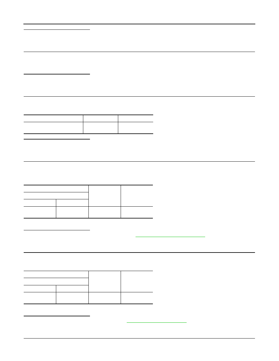
CHECK COOLING FAN RELAY OUTPUT VOLTAGE-2

1. Turn power switch ON.

2. Check the voltage between fuse terminal and ground.

Is the inspection result normal?

YES

>> GO TO 7.

NO

>> GO TO 6.

6.

CHECK M/C RELAY OUTPUT CIRCUIT

1. Turn power switch OFF.

2. Remove M/C relay.

3. Check the continuity between M/C relay harness connector terminal and fuse harness connector.

4. Also check harness for short to ground and short to power.
Is the inspection result normal?

YES

>> Check M/C relay routing circuit. Refer to 

EVC-371, "Diagnosis Procedure"

.

NO

>> Repair or replace error-detected parts.

7.

CHECK COOLING FAN CONTROL MODULE POWER SUPPLY CIRCUIT 

1. Turn power switch OFF.

2. Check the continuity between cooling fan relay harness connector and fuse terminal.

3. Also check harness for short to ground and short to power.
Is the inspection result normal?

YES

>> Check intermittent incident. Refer to 

GI-53, "Intermittent Incident"

.

NO

>> Repair or replace error-detected parts.

8.

CHECK COOLING FAN RELAY GROUND CIRCUIT

1. Turn power switch OFF.

+

Voltage

#73 fuse terminal

Ground

12V battery volt-

age

+

Continuity

M/C relay

Connector

Terminal

E65

5

#73 fuse termi-

nal

Existed

+

Continuity

Cooling fan relay

Connector

Terminal

E18

1

#73 fuse termi-

nal

Existed

COOLING FAN

EVC-369

< DTC/CIRCUIT DIAGNOSIS >

D

E

F

G

H

I

J

K

L

M

A

B

EVC

N

O

P

2. Check the continuity between cooling fan relay harness connector and ground.

Is the inspection result normal?

YES

>> GO TO 9.

NO

>> Repair or replace error-detected parts.

9.

CHECK COOLING FAN CONTROL MODULE POWER SUPPLY CIRCUIT

1. Check the continuity between cooling fan relay harness connector and cooling fan control module harness

connector.

2. Also check harness for short to ground.
Is the inspection result normal?

YES

>> GO TO 10.

NO

>> Repair or replace error-detected parts.

10.

CHECK COOLING FAN RELAY

Refer to 

EVC-370, "Component Inspection (Cooling Fan Relay)"

.

Is the inspection result normal?

YES

>> Check intermittent incident. Refer to 

GI-53, "Intermittent Incident"

.

NO

>> Replace cooling fan relay.

11.

CHECK COOLING FAN CONTROL MODULE GROUND CIRCUIT

1. Turn power switch OFF.

2. Check the continuity between cooling fan control module harness connector and ground.

Is the inspection result normal?

YES

>> GO TO 12.

NO

>> Repair or replace error-detected parts.

12.

CHECK COOLING FAN MOTOR 1 AND 2

Check cooling fan motor. Refer to 

EVC-370, "Component Inspection (Cooling Fan Motor)"

.

Is the inspection result normal?

YES

>> GO TO 13.

NO

>> Replace malfunctioning cooling fan motor. Refer to 

HCO-22, "Exploded View"

.

13.

CHECK COOLING FAN CONTROL SIGNAL CIRCUIT

1. Disconnect VCM harness connector.

2. Check the continuity between cooling fan control module harness connector and VCM harness connector.

+

Continuity

Cooling fan relay

Connector

Terminal

E18

2

Ground

Existed

+

Continuity

Cooling fan control module

Cooling fan relay

Connector

Terminal

Connector

Terminal

E19

3

E18

5

Existed

+

Continuity

Cooling fan control module

Connector

Terminal

E19

1

Ground

Existed

EVC-370

< DTC/CIRCUIT DIAGNOSIS >

COOLING FAN

3. Also check harness for short to ground and short to power.
Is the inspection result normal?

YES

>> GO TO 14.

NO

>> Repair or replace error-detected parts.

14.

REPLACE COOLING FAN CONTROL MODULE

1. Replace cooling fan control module. Refer to 

HCO-22, "Exploded View"

.

2. Erase the DTC.

3. Perform component function check. Refer to 

EVC-367, "Component Function Check"

.

Is the inspection result normal?

YES

>> INSPECTION END

NO

>> Replace VCM. Refer to 

EVC-423, "Removal and Installation"

.

Component Inspection (Cooling Fan Motor)

INFOID:0000000010120830

1.

CHECK COOLING FAN MOTOR

1. Turn power switch OFF.

2. Disconnect cooling fan control module harness connectors.

3. Supply cooling fan control module harness connector terminals with 12V battery voltage as per the follow-

ing, and check operation.

Is the inspection result normal?

YES

>> INSPECTION END

NO

>> Replace malfunctioning cooling fan motor. Refer to 

HCO-22, "Removal and Installation"

.

Component Inspection (Cooling Fan Relay)

INFOID:0000000010120831

1.

CHECK COOLING FAN RELAY

1. Turn power switch OFF.

2. Remove cooling fan relay.

3. Check the continuity between cooling fan relay terminals under

the following conditions.

Is the inspection result normal?

YES

>> INSPECTION END

NO

>> Replace cooling fan relay.

+

Continuity

Cooling fan control module

VCM

Connector

Terminal

Connector

Terminal

E19

2

E62

128

Existed

Cooling fan control module

Operation

Motor

Connector

Terminal

+

1

E301

4

5

Cooling fan operates.

2

E302

6

7

Terminals

Conditions

Continuity

3 and 5

12 V direct current supply between terminals 1 and 2

Existed

No current supply

Not existed

MBIB0057E

M/C RELAY

EVC-371

< DTC/CIRCUIT DIAGNOSIS >

D

E

F

G

H

I

J

K

L

M

A

B

EVC

N

O

P

M/C RELAY

Diagnosis Procedure

INFOID:0000000010120832

1.

CHECK BATTERY POWER SUPPLY-1

1. Turn power switch OFF.

2. Disconnect M/C relay.

3. Check the voltage between M/C relay harness connector and ground.

Is the inspection result normal?

YES

>> GO TO 5.

NO

>> GO TO 2.

2.

CHECK FUSIBLE LINK

1. Remove #G fusible link.

2. Check that the fusible link is not fusing.
Is the inspection result normal?

YES

>> GO TO 3.

NO

>> Replace the fusible link after repairing the applicable circuit.

3.

CHECK BATTERY POWER SUPPLY-2

Check the voltage between fusible link harness connector and ground.

Is the inspection result normal?

YES

>> GO TO 4.

NO

>> Check power supply circuit for battery power supply.

4.

CHECK BATTERY POWER SUPPLY CIRCUIT

1. Check the continuity between M/C relay harness connector and fusible link harness connector.

2. Also check harness for short to ground and short to power.
Is the inspection result normal?

YES

>> Check intermittent incident. Refer to 

GI-53, "Intermittent Incident"

.

NO

>> Repair or replace error-detected parts.

5.

CHECK M/C RELAY

Check M/C relay. Refer to 

EVC-372, "Component Inspection (M/C Relay)"

.

Is the inspection result normal?

YES

>> GO TO 6.

+

Voltage

M/C relay

Connector

Terminal

E65

2

Ground

12V battery volt-

age

3

+

Voltage

#G fusible link terminal

Ground

12V battery volt-

age

+

Continuity

M/C relay

Connector

Terminal

#G fusible link 

terminal

E65

2

Existed

3


Content   ..  584  585  586  587   ..