Nissan Leaf. Manual - part 299


  Index      Nissan     Nissan Leaf (2011-2014 year) - Service and Repair Manual


Search            


Content   ..  297  298  299  300   ..


Nissan Leaf. Manual - part 299


FRONT DISC BRAKE

BR-517

< REMOVAL AND INSTALLATION >

C

D

E

G

H

I

J

K

L

M

A

B

BR

N

O

P

3. Remove upper and lower sliding pin bolts. Refer to 

BR-518,

"BRAKE CALIPER ASSEMBLY : Exploded View"

.

NOTE:

Note the pin orientation during removal. The lower sliding pin

contains a bushing.

4. Remove the brake caliper from the torque member. Leaving the brake hose attached, reposition the brake

caliper aside with wire.

CAUTION:

Do not twist or stretch brake hose.

5. Remove the brake pads, shims, and shim covers from the torque member.
6. Remove the brake pad retainers from the torque member.

CAUTION:

When removing the brake pad retainers from the torque

member, lift it in the direction indicated by the arrow as

shown so that it does not deform.

INSTALLATION

Installation is in the reverse order of removal.

• Apply Molykote AS-880N grease or equivalent between the outer brake pad, outer shim cover and outer

shim and between the inner shim and inner brake pad. Install outer shim and outer shim cover to outer brake

pad. Install inner shim and inner shim cover to inner brake pad.
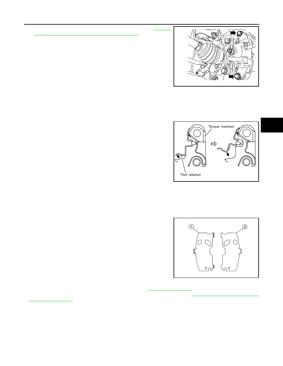
CAUTION:

• The inner shim cover (LH) (1) is different than the inner shim

cover (RH) (2). Install the inner shim covers in the correct

position.

• Replace brake pad shims and covers as a set if any corro-

sion or damage exists.

• Apply Molykote 7439 grease or equivalent between brake pad

retainers and brake pad ends. Install brake pad retainers and

brake pads to torque member.

CAUTION:

• Make sure the brake pad retainers are fastened properly to

the torque member.

• Replace brake pad retainers if damage exists.

• Press the piston into the cylinder bore of the caliper using a suitable tool.

• Check brake fluid level and refill as necessary. Refer to 

BR-493, "Inspection"

.

• Burnish contact surface between brake pads and disc brake rotors. Refer to 

BR-496, "BRAKE PAD : Inspec-

tion and Adjustment"

.

BRAKE PAD : Inspection

INFOID:0000000010123146

INSPECTION AFTER REMOVAL

• Replace the shims and the shim covers if rust is excessively attached.

• Eliminate rust on the pad retainers and the torque member. Replace them if rust is excessively attached.

INSPECTION AFTER INSTALLATION

• Check a drag of front disc brake. If any drag is found, follow the procedure described below.

ALFIA0300ZZ

SBR556E

ALFIA0359ZZ

BR-518

< REMOVAL AND INSTALLATION >

FRONT DISC BRAKE

1. Remove brake pads. Refer to 

BR-516, "BRAKE PAD : Removal and Installation"

.

2. Press the piston. Refer to 

BR-516, "BRAKE PAD : Removal and Installation"

.

3. Install brake pads. Refer to 

BR-516, "BRAKE PAD : Removal and Installation"

.

4. Securely depress the brake pedal several times.
5. Check a drag of front disc brake again. If any drag is found, disassemble the cylinder body and replace if

necessary. Refer to 

BR-520, "BRAKE CALIPER ASSEMBLY : Disassembly and Assembly"

• Burnish contact surfaces brake pads and disc rotor after refinishing or replacing brake pads, or if a soft pedal

occurs at very low mileage. Refer to 

BR-496, "BRAKE PAD : Inspection and Adjustment"

.

BRAKE CALIPER ASSEMBLY
BRAKE CALIPER ASSEMBLY : Exploded View

INFOID:0000000010123147

BRAKE CALIPER ASSEMBLY : Removal and Installation

INFOID:0000000010123148

WARNING:

Clean dust on brake calipers and brake pads with a vacuum dust collector to minimize the hazard of

airborne particles or other materials.

CAUTION:

• While removing brake caliper, do not depress the brake pedal because the piston will pop out. 

• Do not damage piston boot.

• Keep disc brake rotor free from brake fluid.

• Refill the brake reservoir with new brake fluid “DOT 3”.

1.

Union bolt

2.

Copper sealing washer

3.

Brake hose

4.

Cap

5.

Bleeder valve

6.

Sliding pin bolt

7.

Brake caliper

8.

Piston seal

9.

Piston

10. Piston boot

11. Lower sliding pin

12. Upper sliding pin

13. Torque member bolt

14. Sliding pin boot

15. Lower sliding pin bushing

16. Torque member

R.

Rubber grease

NOTE:
RH side caliper shown, LH side caliper similar.

AWFIA1089ZZ

FRONT DISC BRAKE

BR-519

< REMOVAL AND INSTALLATION >

C

D

E

G

H

I

J

K

L

M

A

B

BR

N

O

P

• Do not reuse drained brake fluid.

NOTE:

When removing components such as hoses, tubes/lines, etc., cap or plug openings to prevent fluid from spill-

ing.

REMOVAL

1. Remove front wheel and tire using power tool. Refer to 

WT-45, "Removal and Installation"

.

2. Remove reservoir cap.
3. Remove union bolt (A) and then remove brake hose from brake

caliper assembly. Discard the copper sealing washers.

• Protrusions (B)

CAUTION:

Do not reuse copper sealing washers.

4. Remove the upper and lower sliding pin bolts.

NOTE:

Note the sliding pin orientation during removal. The lower sliding pin contains a bushing.

5. Remove the brake caliper from the torque member.
6. Remove the brake pads and shims from the torque member.
7. Remove torque member bolts and the torque member.

NOTE:

Torque member bolt style may differ between flange bolt and bolt with washer.

8. Remove disc brake rotor. If reusing the disc brake rotor apply

matching marks as shown.

INSTALLATION

Installation is in the reverse order of removal.

• Install brake hose to brake caliper assembly with new copper seal-

ing washers. Align the brake hose tab between the protrusions (B)

on the brake caliper assembly as shown. Tighten union bolt (A) to

the specified torque. Refer to 

BR-503, "FRONT : Exploded View"

.

CAUTION:

Do not reuse copper sealing washers.

• Refill with new brake fluid and bleed air from the brake hydraulic system. Refer to 

BR-494, "Bleeding Brake

System"

.

• Perform inspection after installation. Refer to 

BR-521, "BRAKE CALIPER ASSEMBLY : Inspection"

.

ALFIA0287ZZ

SDIA2608E

ALFIA0287ZZ

BR-520

< REMOVAL AND INSTALLATION >

FRONT DISC BRAKE

BRAKE CALIPER ASSEMBLY : Disassembly and Assembly

INFOID:0000000010123149

DISASSEMBLY

1. Place a wooden block in the brake caliper as shown, and blow

air into the union bolt hole to remove the piston and piston boot.

WARNING:

Do not get fingers caught between the piston and wooden

block.

2. Remove the piston seal from the brake caliper using a suitable

tool. Discard the piston seal.

CAUTION:

• Be careful not to damage the cylinder inner wall.

• Do not reuse the piston seal.

ASSEMBLY

CAUTION:

Use NISSAN Rubber Grease during assembly.
1. Apply rubber grease to new piston seal (1), and install on brake

caliper.

CAUTION:

Do not reuse piston seal.

2. Apply rubber grease to new piston boot (1). Cover the piston (2)

end with new piston boot, and then install cylinder side lip on

new piston boot securely into a groove on brake caliper.

CAUTION:

Do not reuse piston boot.

BRD0041D

JPFIA0038ZZ

JPFIA0039ZZ

JPFIA0040ZZ


Content   ..  297  298  299  300   ..