Nissan Leaf. Manual - part 176
SYSTEM
BR-25
< SYSTEM DESCRIPTION >
C
D
E
G
H
I
J
K
L
M
A
B
BR
N
O
P
- For Canada
• The brake system warning lamp warns the driver of malfunction in hill start assist function.
NOTE:
The brake system warning lamp may turn ON simultaneously with the brake warning lamp. For details, refer to
BULB CHECK
Several seconds after power switch is turned ON
SYNCHRONIZATION WITH WARNING BUZZER
YES
For warning buzzer, refer to
SYNCHRONIZATION WITH MASTER WARNING LAMP
Not applicable
OPERATION AT COMBINATION METER CAN COMMUNICATION CUT-OFF OR UNUSUAL SIG-
NAL
For actions on CAN communications blackout in the combination meter, refer to
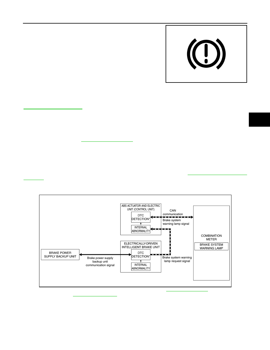
SYSTEM DIAGRAM
*: For DTCs that the brake system warning lamp turns ON, refer to
(electrically-driven
intelligent brake unit) or
[ABS actuator and electric unit (control unit)].
SIGNAL PATH
• The electrically-driven intelligent brake unit transmits a brake system warning lamp request signal to the
ABS actuator and electric unit (control unit) via CAN communication when detecting a malfunction in the
electrically-driven intelligent brake unit.
• The ABS actuator and electric unit (control unit) receiving a brake system warning lamp request signal, and
transmits a brake system warning lamp signal to the combination meter via CAN communication.
JPNIA1872ZZ
JSFIA1850GB