Content .. 1273 1274 1275 1276 ..
Nissan Leaf. Manual - part 1275
WCS
COMBINATION METER
WCS-27
< ECU DIAGNOSIS INFORMATION >
C
D
E
F
G
H
I
J
K
L
M
B
A
O
P
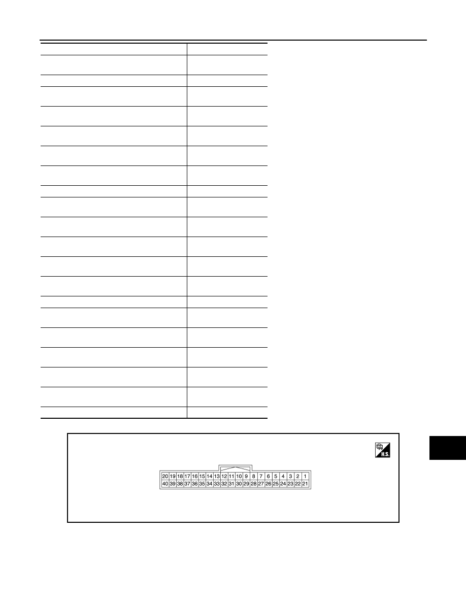
TERMINAL LAYOUT
PHYSICAL VALUES
• ECO tree (2) illuminates
• 5 segments of ECO tree (1) illuminate
SEG15+SEG21
ECO tree (3) illuminates
SEG22
• ECO tree (3) illuminates
• 1 segment of ECO tree (1) illuminate
SEG11+SEG22
• ECO tree (3) illuminates
• 2 segments of ECO tree (1) illuminate
SEG12+SEG22
• ECO tree (3) illuminates
• 3 segments of ECO tree (1) illuminate
SEG13+SEG22
• ECO tree (3) illuminates
• 4 segments of ECO tree (1) illuminate
SEG14+SEG22
• ECO tree (3) illuminates
• 5 segments of ECO tree (1) illuminate
SEG15+SEG22
ECO tree (4) illuminates
SEG23
• ECO tree (4) illuminates
• 1 segment of ECO tree (1) illuminate
SEG11+SEG23
• ECO tree (4) illuminates
• 2 segments of ECO tree (1) illuminate
SEG12+SEG23
• ECO tree (4) illuminates
• 3 segments of ECO tree (1) illuminate
SEG13+SEG23
• ECO tree (4) illuminates
• 4 segments of ECO tree (1) illuminate
SEG14+SEG23
• ECO tree (4) illuminates
• 5 segments of ECO tree (1) illuminate
SEG15+SEG23
ECO tree (5) illuminates
SEG24
• ECO tree (5) illuminates
• 1 segment of ECO tree (1) illuminate
SEG11+SEG24
• ECO tree (5) illuminates
• 2 segments of ECO tree (1) illuminate
SEG12+SEG24
• ECO tree (5) illuminates
• 3 segments of ECO tree (1) illuminate
SEG13+SEG24
• ECO tree (5) illuminates
• 4 segments of ECO tree (1) illuminate
SEG14+SEG24
• ECO tree (5) illuminates
• 5 segments of ECO tree (1) illuminate
SEG15+SEG24
Other than the above
Off
Displays number of ON segments of ECO tree
Status
JSNIA3729ZZ