Content .. 1222 1223 1224 1225 ..
Nissan Leaf. Manual - part 1224
B2801 QUICK CHARGE CONNECTOR
VC-63
< DTC/CIRCUIT DIAGNOSIS >
D
E
F
G
H
I
J
K
L
M
A
B
VC
N
O
P
3.
CHECK QUICK CHARGE PORT
Check the quick charge port. Refer to
.
Is the inspection result normal?
YES
>> GO TO 4.
NO
>> Replace quick charge port. Refer to
VC-128, "Removal and Installation"
.
4.
CHECK QUICK CHARGER CONNECTION SIGNAL POWER SUPPLY (1)
Check the voltage between quick charge port harness connector terminals.
Is the inspection result normal?
YES
>> GO TO 8.
NO
>> GO TO 5.
5.
CHECK QUICK CHARGER CONNECTION SIGNAL POWER SUPPLY (2)
Check the voltage between quick charge port harness connector and ground.
Is the inspection result normal?
YES
>> GO TO 7.
NO
>> GO TO 6.
6.
CHECK QUICK CHARGER CONNECTION SIGNAL POWER SUPPLY CIRCUIT
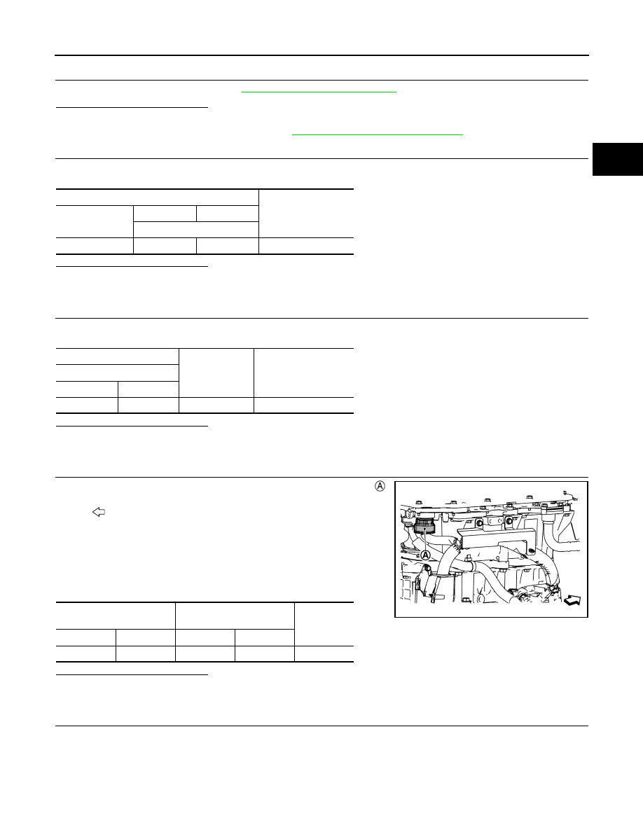
1. Disconnect PDM (Power Delivery Module) harness connector .
NOTE:
Loosen the PDM (Power Delivery Module) harness connector by
rotating it counterclockwise and remove it.
2. Check the continuity between quick charge port harness con-
nector and PDM (Power Delivery Module) harness connector.
Is the inspection result normal?
YES
>> GO TO 9.
NO
>> Repair or replace error-detected parts.
7.
CHECK QUICK CHARGER CONNECTION SIGNAL GROUND CIRCUIT
Check the continuity between quick charge port harness connector and ground.
Quick charge port
Voltage
Connector
+
−
Terminal
E7
3
5
12V battery voltage
+
−
Voltage
Quick charge port
Connector
Terminal
E7
3
Ground
12V battery voltage
: Vehicle front
Quick charge port
PDM
(Power Delivery Module)
Continuity
Connector
Terminal
Connector
Terminal
E7
3
F23
20
Existed
JSCIA0693ZZ