Content .. 1184 1185 1186 1187 ..
Nissan Leaf. Manual - part 1186
TRACTION MOTOR INVERTER
TMS-25
< ECU DIAGNOSIS INFORMATION >
D
E
F
G
H
I
J
K
L
M
A
B
TMS
N
O
P
• Check them with vehicle side harness connector, removing traction motor inverter connector. Never
touch terminals of traction motor inverter side connector at this operation.
• If power switch is pushed ON with traction motor inverter connector removed, other control modules
might detect malfunction of traction motor inverter.
Fail-safe
INFOID:0000000010120913
Terminal No.
(Color)
Description
Condition
Value (Approx.)
+
−
Signal name
Input/
Output
14
(L)
—
EV system CAN-H
Input/
Output
—
—
15
(G)
—
EV system CAN-L
Input/
Output
—
—
18
(L)
17
(P)
Traction motor resolver
signal (S2 – S4)
Input
Power switch OFF
20 – 35
Ω
19
(R)
27
(G)
Traction motor resolver
signal (R1 – R2)
Output
Power switch OFF
8 – 15
Ω
20
(B)
21
(W)
Traction motor resolver
signal (S1 – S3)
Input
Power switch OFF
20 – 35
Ω
42
(LG)
Ground
Power ON power sup-
ply
—
Power switch ON
9 – 16 V
Power switch OFF
0 V
45
(Y)
44
(O)
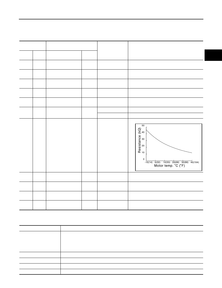
Traction motor tempera-
ture sensor
Input
Power switch OFF
Within
± 50% of temperature characteristics diagram
46
(G)
Ground
12V battery power sup-
ply
—
Power switch ON
9 – 16 V
47
(B)
Ground GND
—
Always
0 V
48
(G)
Ground
12V battery power sup-
ply
—
Power switch ON
9 – 16 V
49
(B)
Ground GND
—
Always
0 V
JPCIA0030GB
DTC
Vehicle behavior
P0A1B
Any of the following statuses is observed.
• No impact to vehicle behavior
• Stops drive control of traction motor
• Stops drive control of traction motor, and requires system main relay OFF to VCM
• Limits the maximum torque of traction motor to 40% or less
P0A2C
Limits the maximum torque of traction motor to 40% or less
P0A2D
Limits the maximum torque of traction motor to 40% or less
P0A2F
Stops drive control of traction motor
P0A3F
Stops drive control of traction motor