Nissan Leaf. Manual - part 1159


  Index      Nissan     Nissan Leaf (2011-2014 year) - Service and Repair Manual


Search            


Content   ..  1157  1158  1159  1160   ..


Nissan Leaf. Manual - part 1159


TM-42

< SYSTEM DESCRIPTION >

[ELECTRIC SHIFT]

SYSTEM

SYSTEM

ELECTRIC SHIFT SYSTEM
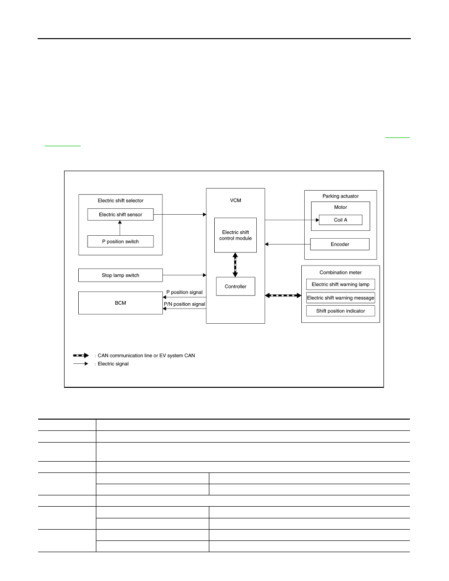
ELECTRIC SHIFT SYSTEM : System Description

INFOID:0000000010119555

• The electric shift system detects each shift position electrically. In addition, in P position, the electric shift

system activates the parking actuator, according to electrical signals received from the P position switch and

brings the vehicle into the parking state.

• In the event of a malfunction in the electric shift system, the shift position indicator (in the combination meter)

turns OFF and only the selector indicator (in the electric shift selector area) indicates the shift position.

• In the event of a malfunction in the electric shift system, the system enters fail-safe mode. Refer to 

TM-49,

"Fail-Safe"

.

SYSTEM DIAGRAM

ELECTRIC SHIFT SYSTEM : Fail-Safe

INFOID:0000000010119556

JSDIA4217GB

DTC

Vehicle behavior

P0571

No impact to vehicle behavior

P0705

When shifting to the R position and the D position, the reaction becomes slower and it takes approximately 1 sec-
ond to complete shifting

P0706

Shifting to the R position, N position and D position is prohibited

P0780

Malfunction in P position

Shifting from the P position to another position is prohibited

Malfunction in position other than P

Shifting to the P position is prohibited

P1722

No impact to vehicle behavior

P1802

Malfunction in P position

Shifting from the P position to another position is prohibited

Malfunction in position other than P

Shifting to the P position is prohibited

P1803

Malfunction in P position

Shifting from the P position to another position is prohibited

Malfunction in position other than P

Shifting to the P position is prohibited

SYSTEM

TM-43

< SYSTEM DESCRIPTION >

[ELECTRIC SHIFT]

C

E

F

G

H

I

J

K

L

M

A

B

TM

N

O

P

ELECTRIC SHIFT SYSTEM : Protection Control

INFOID:0000000010119557

If shifting from the P position to another position and shifting from another position to the P position are

repeated within a short period of time, it may become impossible to shift for system protection. In this case, the

system automatically returns to the normal state allowing shifting after approximately 10 seconds.

WARNING/INDICATOR/CHIME LIST
WARNING/INDICATOR/CHIME LIST : Warning Lamp/Indicator Lamp

INFOID:0000000010119558

P1804

No impact to vehicle behavior

P1811

Automatic P position system is disabled

P1895

No impact to vehicle behavior

P1896

When shifting to the R position and the D position, the reaction becomes slower and it takes approximately 1 sec-
ond to complete shifting

P1897

No impact to vehicle behavior

P1899

Malfunction in P position

Shifting from the P position to another position is prohibited

Malfunction in position other than P

Shifting to the P position is prohibited

P189A

Malfunction in P position

Shifting from the P position to another position is prohibited

Malfunction in position other than P

Shifting to the P position is prohibited

P189D

No impact to vehicle behavior

P18A3

Malfunction in P position

Shifting from the P position to another position is prohibited

Malfunction in position other than P

Shifting to the P position is prohibited

P18A4

Malfunction in P position

Shifting from the P position to another position is prohibited

Malfunction in position other than P

Shifting to the P position is prohibited

P18A7

Shifting operation is prohibited

P18A8

Pushing the P position switch does not switch the to the P position

P18A9

Malfunction in P position

Shifting from the P position to another position is prohibited

Malfunction in position other than P

Shifting to the P position is prohibited

P18AB

Automatic P position system may be disabled

P18AC

No impact to vehicle behavior

P18AE

No impact to vehicle behavior

P18AF

No impact to vehicle behavior

P18B0

Malfunction in P position

Shifting from the P position to another position is prohibited

Malfunction in position other than P

Shifting to the P position is prohibited

P18B1

Malfunction in P position

Shifting from the P position to another position is prohibited

Malfunction in position other than P

Shifting to the P position is prohibited

P18B2

Malfunction in P position

Shifting from the P position to another position is prohibited

Malfunction in position other than P

Shifting to the P position is prohibited

U1000

EV system CAN with VCM blocked

Shifting to the R position and the D position is prohibited

Other than the above

No impact to vehicle behavior

U1010

Shifting to the R position and the D position is prohibited

U1086

No impact to vehicle behavior

DTC

Vehicle behavior

Name

Design

Arrangement/Function

Electric shift warning lamp

Regarding the arrangement. Refer to 

MWI-6, "METER SYSTEM : Combination 

Meter"

.

Regarding the function. Refer to 

TM-35, "Electric Shift Warning Lamp"

.

TM-44

< SYSTEM DESCRIPTION >

[ELECTRIC SHIFT]

SYSTEM

WARNING/INDICATOR/CHIME LIST : Warning/Indicator (On Information Display)

INFOID:0000000010119559

WARNING/INDICATOR/CHIME LIST : Warning Chime

INFOID:0000000010119560

Master warning lamp

Regarding the arrangement. Refer to 

MWI-6, "METER SYSTEM : Combination 

Meter"

.

Regarding the function. Refer to 

MWI-31, "MASTER WARNING LAMP : Sys-

tem Description"

.

Name

Design

Arrangement/Function

Name

Function

Shift position indicator

Refer to 

TM-38, "Shift Position Indicator"

.

Electric shift warning message

Refer to 

TM-36, "Electric Shift Warning Message"

.

Name

Function

Shift position warning buzzer

Refer to 

TM-39, "Shift Position Warning Buzzer"

.

DIAGNOSIS SYSTEM (ELECTRIC SHIFT)

TM-45

< SYSTEM DESCRIPTION >

[ELECTRIC SHIFT]

C

E

F

G

H

I

J

K

L

M

A

B

TM

N

O

P

DIAGNOSIS SYSTEM (ELECTRIC SHIFT)

DIAGNOSIS DESCRIPTION
DIAGNOSIS DESCRIPTION : System Description

INFOID:0000000010119561

This is an on-board trouble diagnosis system which automatically detects malfunction. Detected malfunction is

memorized in ECU as DTC. Diagnosis information can be confirmed using CONSULT.

DIAGNOSIS DESCRIPTION : DTC

INFOID:0000000010119562

• DTC (P0571, P0705, P0780, etc.) is specified by SAE J2012/ISO 15031-6.

• Electric shift control module memorizes DTC when malfunction is detected. It can memorize plural DTCs.

DIAGNOSIS DESCRIPTION : Counter System

INFOID:0000000010119563

Counter system counts up at every operation of  power switch from OFF to ON under condition that the same

malfunction is not detected. On the other hand, if the same DTC as memorized one is detected again, the

count is reset and the counter system counts up again from “0”.

CONSULT Function

INFOID:0000000010119564

APPLICABLE ITEMS

SELF DIAGNOSTIC RESULTS

Display Item List

Refer to 

TM-50, "DTC Index"

.

How to Read DTC

DTC is displayed on “Self Diagnostic results” of CONSULT.

When DTC is currently detected, “CRNT” is displayed. If “PAST” is displayed, it shows a malfunction occurred

in the past.The trip number of drive without malfunction of concerned DTC can be confirmed with “IGN

counter” inside “FFD”.

How to Erase DTC

NOTE:

If the power switch is kept ON after repair operation, operate the power switch to OFF. Operate the power

switch to ON again after waiting at least 10 seconds.

1. Touch “SHIFT” of CONSULT.

2. Touch “Self Diagnostic Result”.

3. Touch “Erase”. (DTC memorized in electric shift control module is erased.)

IGN Counter

IGN counter is displayed in “FFD”. It displays the number of operations of power switch from OFF to ON after

DTC recovery to normal.

• If malfunction (DTC) is currently detected, “0” is displayed.

• The displayed number counts up at each operation of power switch from OFF to ON after recovery to nor-

mal, such as 1 

→ 2 → 3...38 → 39.

• If the number of operation exceeds 39, the displayed number will be fixed at “39” until the self diagnosis

result is erased.

DATA MONITOR

Mode

Function description

All DTC Reading

Display all DTCs or diagnostic items that all ECUs are recording and judging

Self Diagnostic Results

Retrieve DTC from ECU and display diagnostic items. 

Data Monitor

Monitor the input/output signal of the control unit in real time.

CAN Diagnosis

This mode displays a network diagnosis result about CAN by diagram. 

CAN Diagnosis Support Monitor

It monitors the status of CAN communication. 

ECU Identification

Display the ECU identification number (part number etc.) of the selected system.


Content   ..  1157  1158  1159  1160   ..