Nissan Primera P11. Manual - part 342
YEL196C
Preceding
page
Preceding
page
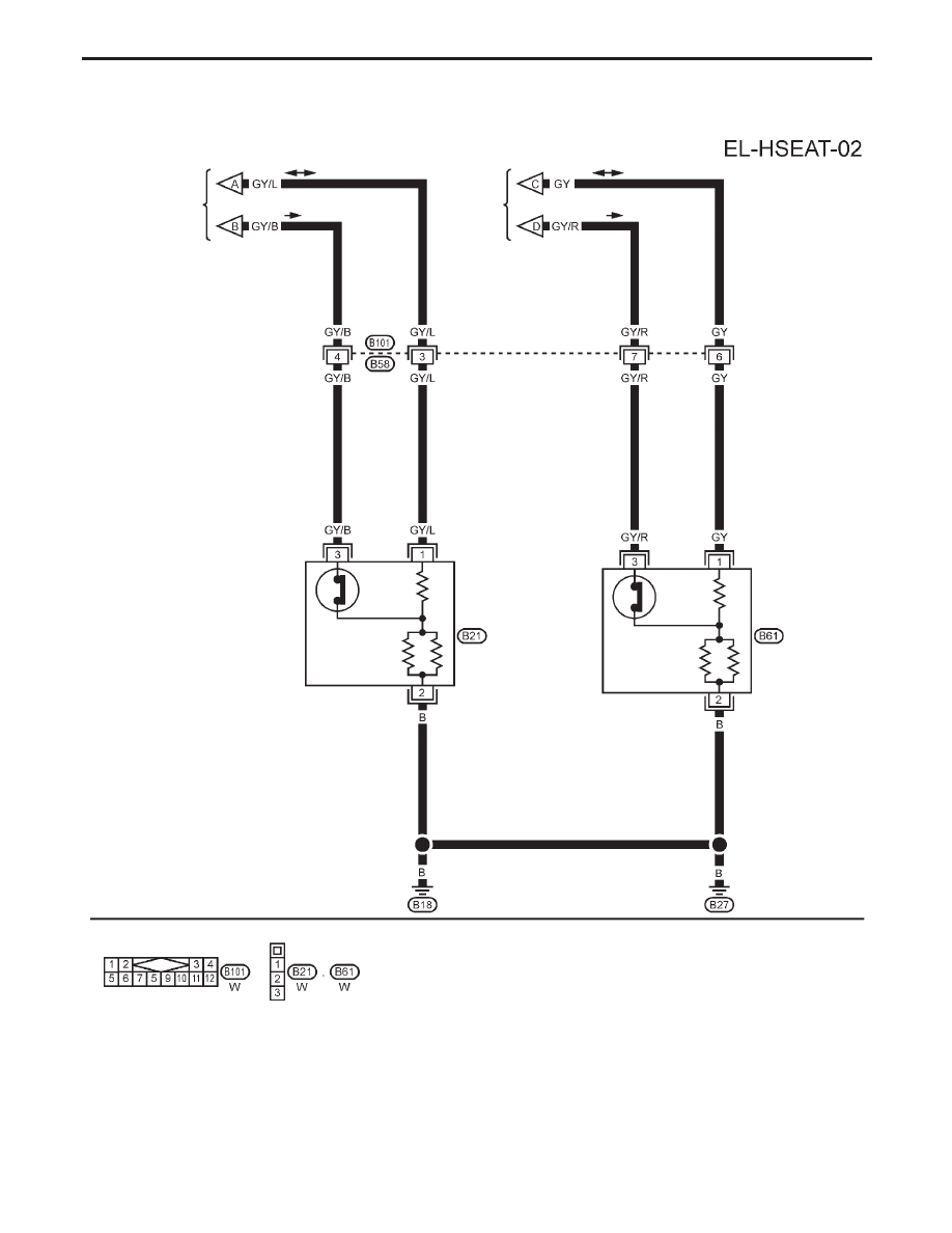
THERMOSTAT
SWITCH
HEATED
SEAT LH
THERMOSTAT
SWITCH
HEATED
SEAT RH
HEATED SEAT
Heated Seat/Wiring Diagram — HSEAT —
(Cont’d)
EL-235
|
|
|
YEL196C Preceding Preceding THERMOSTAT HEATED THERMOSTAT HEATED HEATED SEAT Heated Seat/Wiring Diagram — HSEAT — (Cont’d) EL-235 |