Nissan Primera P11. Manual - part 39
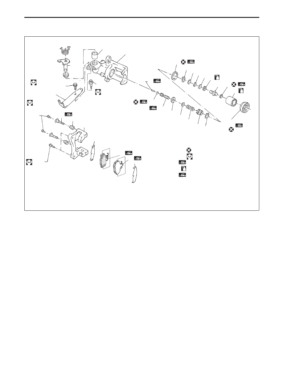
Component
1.
Cable guide
2.
Cylinder
3.
Toggle lever
4.
Pin
5.
Pin boot
6.
Torque member
7.
Inner shim
8.
Inner pad
9.
Outer pad
10. Outer shim
11. Strut
12. O-ring
13. Push rod
14. Key plate
15. Retaining washer
16. Spring
17. Spring cover
18. Snap ring B
19. Piston seal
20. Snap ring A
21. Washer
22. Wave washer
23. Washer
24. Bearing
25. Adjuster
26. Cup
27. Piston
28. Piston boot
29. Sleeve
Pad Replacement
WARNING:
Clean brake pads with a vacuum dust collector to minimize
the hazard of airborne particles or other materials.
CAUTION:
●
When cylinder body is open, do not depress brake pedal
because piston will pop out.
●
Be careful not to damage piston boot or get oil on rotor.
Always replace shims in replacing pads.
●
If shims are rusted or show peeling of rubber coat,
replace them with new shims.
NBR366
SEC. 440
Stopper bolt
10 - 12
(1.0 - 1.2, 7 - 9)
31 - 38
(3.2 - 3.8, 23 - 28)
p
1
22 - 32
(2.3 - 3.2,
17 - 23)
38 - 52
(3.9 - 5.3, 28 - 38)
p
10
p
9
p
P
p
8
p
P
p
7
p
6
p
5
p
4
p
P
to sliding portion
p
12
p
R
p
13
p
R
p
14
p
15
p
16
p
17
p
18
p
28
p
R
: Do not re-use
: N·m (kg-m, ft-lb)
p
R
: Rubber grease point
p
B
: Brake fluid point
p
P
: PBC (Poly Butyl Cuprysil) grease
or silicone-based grease point
p
23
p
27
p
B
p
26
p
R
p
25
p
24
p
B
p
22
p
21
p
20
p
19
p
R
p
11
p
R
p
3
p
2
p
29
REAR DISC BRAKE TYPE 1
BR-33