Nissan Frontier D22. Manual - part 750


  Index      Nissan     Nissan Frontier D22 Pickup (1998-2004 year) - Service and Repair Manual


Search            


Content   ..  748  749  750  751   ..


Nissan Frontier D22. Manual - part 750


GI-32

SERVICE INFORMATION FOR ELECTRICAL INCIDENT

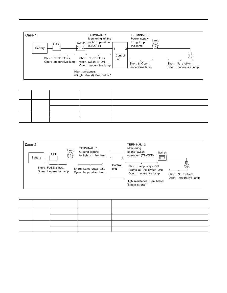
Control Unit Circuit Test 

System Description:When the switch is ON, the control unit lights up the lamp.

INPUT-OUTPUT VOLTAGE CHART

The voltage value is based on the body ground.
*:If high resistance exists in the switch side circuit (caused by a single strand), terminal 1 does not detect battery voltage. Control unit
does not detect the switch is ON even if the switch does not turn ON. Therefore, the control unit does not supply power to light up the
lamp.

INPUT-OUTPUT VOLTAGE CHART

The voltage value is based on the body ground.
*:If high resistance exists in the switch side circuit (caused by a single strand), terminal 2 does not detect approx. 0V. Control unit does
not detect the switch is ON even if the switch does not turn ON. Therefore, the control unit does not control ground to light up the lamp.

MGI034A

Pin 

No.

Item

Condition

Voltage

value [V]

In case of high resistance such as single strand [V] *

1

Switch

Switch ON

Battery voltage

Lower than battery voltage Approx. 8 (Example)

Switch OFF

Approx. 0

Approx. 0

2

Lamp

Switch ON

Battery voltage

Approx. 0 (Inoperative lamp)

Switch OFF

Approx. 0

Approx. 0

MGI035A

Pin 

No.

Item

Condition

Voltage

value [V]

In case of high resistance such as single strand [V] *

1

Lamp

Switch ON

Approx. 0

Battery voltage (Inoperative lamp)

Switch OFF

Battery voltage

Battery voltage

2

Switch

Switch ON

Approx. 0

Higher than 0 Approx. 4 (Example)

Switch OFF

Approx. 5

Approx. 5

SERVICE INFORMATION FOR ELECTRICAL INCIDENT

GI-33

C

D

E

F

G

H

I

J

K

L

M

B

GI

Control Units and Electrical Parts

EAS0012M

PRECAUTIONS

Never reverse polarity of battery terminals.

Install only parts specified for a vehicle.

Before replacing the control unit, check the input and output and
functions of the component parts. 

Do not apply excessive force when disconnecting a connector.

If a connector is installed by tightening bolts, loosen bolt mount-
ing it, then take it out by hand.

Before installing a connector, make sure the terminal is not bent
or damaged, and then correctly connect it.
When installing a connector by tightening bolts, fix it by tighten-
ing the mounting bolt until the painted projection of the connec-
tor becomes even with the surface. 

For removal of the lever type connector, pull the lever up to the
direction pointed to by the arrow A in the figure, and then
remove the connector. 

For installation of the lever type connector, pull down the lever to
the direction pointed by the arrow B in the figure, and then push
the connector until a clicking noise is heard.

SAIA0251E

SAIA0252E

SAIA0253E

SAIA0254E

GI-34

SERVICE INFORMATION FOR ELECTRICAL INCIDENT

Do not apply excessive shock to the control unit by dropping or
hitting it.

Be careful to prevent condensation in the control unit due to
rapid temperature changes and do not let water or rain get on it.
If water is found in the control unit, dry it fully and then install it in
the vehicle.

Be careful not to let oil to get on the control unit connector.

Avoid cleaning the control unit with volatile oil.

Do not disassemble the control unit, and do not remove the
upper and lower covers.

When using a DMM, be careful not to let test probes get close to
each other to prevent the power transistor in the control unit
from damaging battery voltage because of short circuiting.

When checking input and output signals of the control unit, use
the specified check adapter.

SMJ INSTALLATION

To install SMJ, tighten bolts until orange “fulltight” mark appears and
then retighten to specified torque as required.

CAUTION:

Do not overtighten bolts, otherwise, they may be damaged.

SAIA0255E

SEF348N

SMJ

:3 - 5 N·m (0.3 - 0.5 kg-m, 26 - 43 in-lb)

CEL969

CONSULT-II CHECKING SYSTEM

GI-35

C

D

E

F

G

H

I

J

K

L

M

B

GI

CONSULT-II CHECKING SYSTEM

PFP:00000

Description

EAS0012N

CONSULT-II is a hand-held type tester.  When it is connected with a diagnostic connector equipped on the
vehicle side, it will communicate with the control unit equipped in the vehicle and then enable various
kinds of diagnostic tests.

Refer to “CONSULT Operator's Manual” for more information.

Function and System Application

EAS0012O

x: Applicable
*: For VG33E and VG33ER engine

Nickel Metal Hydride Battery Replacement 

EAS0012P

CONSULT-II contains a nickel metal hydride battery. When replacing the battery obey the following:

WARNING:

Replace the nickel metal hydride battery with Genuine CONSULT-II battery only. Use of another bat-
tery may present a risk of fire or explosion. The battery may present a fire or chemical burn hazard if
mistreated. Do not recharge, disassemble or dispose of in fire.
Keep the battery out of reach of children and discard used battery conforming to the local regulations.

Checking Equipment

EAS0012Q

When ordering the below equipment, contact your NISSAN distributor.

Diagnostic test 

mode

Function

Engine

A/T

Air bag

ABS

ABS 

(Including 

VDC)

Air

Pressure 

Monitor

Work support

This mode enables a technician to 
adjust some devices faster and more 
accurately by following the indica-
tions on CONSULT-II.

x

x

x

DTC work
support

Select the operating condition to 
confirm Diagnosis Trouble Codes.

x

Self-diagnostic 
results

Self-diagnostic results can be read 
and erased quickly.

x

x

x

x

x

x

Trouble diag-
nostic record

Current self-diagnostic results and 
all trouble diagnostic records previ-
ously stored can be read.

x

ECU discrimi-
nated No.

Classification number of a replace-
ment ECU can be read to prevent an 
incorrect ECU from being installed.

x

Data monitor

Input/Output data in the ECU (ECM) 
can be read.

x

x

x

x

x

Data monitor 
(Spec.)

The specified values will be dis-
played when an OK/NG judgment is 
difficult for the DATA MONITOR 
items by Bar Chart and Line Graph.

x

Active test

Diagnostic Test Mode in which CON-
SULT-II drives some actuators apart 
from the ECUs and also shifts some 
parameters in a specified range.

x

x

x

SRT & DTC 
confirmation

The results of SRT (System Readi-
ness Test) and the self-diagnosis 
status/result can be confirmed.

x

x*

ECU (ECM) 
part number

ECU (ECM) part number can be 
read.

x

x

x

x

x


Content   ..  748  749  750  751   ..