Nissan Frontier D22. Manual - part 394
 

  Index      Nissan     Nissan Frontier D22 Pickup (1998-2004 year) - Service and Repair Manual


Search            


Content   ..  392  393  394  395   ..


Nissan Frontier D22. Manual - part 394


TROUBLE DIAGNOSIS

EC-679

[VG33E]

C

D

E

F

G

H

I

J

K

L

M

A

EC

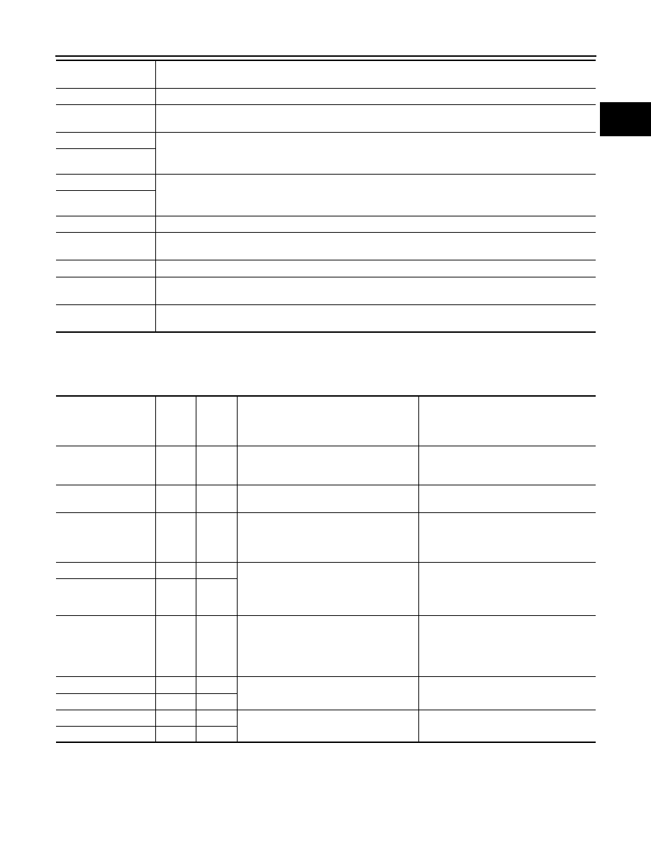
*: The items are the same as those of 1st trip freeze frame data.

DATA MONITOR MODE
Monitored Item

×: Applicable

CAL/LD VALUE [%]

The calculated load value at the moment a malfunction is detected is displayed.

COOLANT TEMP [

°C] 

or [

°F]

The engine coolant temperature at the moment a malfunction is detected is displayed.

S-FUEL TRM-B1 [%]

“Short-term fuel trim” at the moment a malfunction is detected is displayed.

The short-term fuel trim indicates dynamic or instantaneous feedback compensation to the base fuel 
schedule.

S-FUEL TRM-B2 [%]

L-FUEL TRM-B1 [%]

“Long-term fuel trim” at the moment a malfunction is detected is displayed.

The long-term fuel trim indicates much more gradual feedback compensation to the base fuel schedule 
than short-term fuel trim.

L-FUEL TRM-B2 [%]

ENGINE SPEED [rpm]

The engine speed at the moment a malfunction is detected is displayed.

VHCL SPEED [km/h] 
or [mph]

The vehicle speed at the moment a malfunction is detected is displayed.

ABSOL TH·P/S [%]

The throttle valve opening angle at the moment a malfunction is detected is displayed.

B/FUEL SCHDL 
[msec]

The base fuel schedule at the moment a malfunction is detected is displayed.

INT/A TEMP SE [

°C] 

or [

°F]

The intake air temperature at the moment a malfunction is detected is displayed.

Freeze frame data 

item *

Description

Monitored item [Unit]

ECM 

INPUT 

SIG-

NALS

MAIN 

SIG-

NALS

Description

Remarks

ENG SPEED [rpm]

×

×

Indicates the engine speed computed 
from the REF signal (120

° signal) of the 

camshaft position sensor.

MAS A/F SE-B1 [V]

×

×

The signal voltage of the mass air flow 
sensor is displayed.

When the engine is stopped, a certain 
value is indicated.

B/FUEL SCHDL 
[msec]

×

“Base fuel schedule” indicates the fuel 
injection pulse width programmed into 
ECM, prior to any learned on board cor-
rection.

A/F ALPHA-B1 [%]

×

The mean value of the air-fuel ratio feed-
back correction factor per cycle is indi-
cated.

When the engine is stopped, a certain 
value is indicated.

This data also includes the data for the 
air-fuel ratio learning control.

A/F ALPHA-B2 [%]

×

COOLAN TEMP/S 
[

°C] or [°F]

×

×

The engine coolant temperature (deter-
mined by the signal voltage of the engine 
coolant temperature sensor) is dis-
played.

When the engine coolant temperature 
sensor is open or short-circuited, ECM 
enters fail-safe mode. The engine cool-
ant temperature determined by the 
ECM is displayed.

HO2S1 (B1) [V]

×

×

The signal voltage of the heated oxygen 
sensor 1 is displayed.

HO2S1 (B2) [V]

×

×

HO2S2 (B1) [V]

×

×

The signal voltage of the heated oxygen 
sensor 2 is displayed.

HO2S2 (B2) [V]

×

×

EC-680

[VG33E]

TROUBLE DIAGNOSIS

HO2S1 MNTR (B1) 
[RICH/LEAN]

×

Display of heated oxygen sensor 1 signal 
during air-fuel ratio feedback control:
RICH: means the mixture became “rich”, 
and control is being affected toward a 
leaner mixture.
LEAN: means the mixture became 
“lean”, and control is being affected 
toward a rich mixture.

After turning ON the ignition switch, 
“RICH” is displayed until air-fuel mixture 
ratio feedback control begins.

When the air-fuel ratio feedback is 
clamped, the value just before the 
clamping is displayed continuously.

HO2S1 MNTR (B2) 
[RICH/LEAN]

×

HO2S2 MNTR (B1) 
[RICH/LEAN]

×

Display of heated oxygen sensor 2 sig-
nal:
RICH: means the amount of oxygen after 
three way catalyst is relatively small.
LEAN: means the amount of oxygen 
after three way catalyst is relatively large.

When the engine is stopped, a certain 
value is indicated.

HO2S2 MNTR (B2) 
[RICH/LEAN]

×

VHCL SPEED SE
[km/h] or [mph]

×

×

The vehicle speed computed from the 
vehicle speed sensor signal is displayed.

BATTERY VOLT [V]

×

×

The power supply voltage of ECM is dis-
played.

THRTL POS SEN [V]

×

×

The throttle position sensor signal volt-
age is displayed.

FUEL T/TMP SE
[

°C] or [°F]

×

The fuel temperature judged from the 
fuel tank temperature sensor signal volt-
age is displayed.

INT/A TEMP SE
[

°C] or [°F]

×

×

The intake air temperature determined 
by the signal voltage of the intake air 
temperature sensor is indicated.

EVAP SYS PRES [V]

The signal voltage of EVAP control sys-
tem pressure sensor is displayed.

EGR TEMP SEN [V]

×

×

The signal voltage of the EGR tempera-
ture sensor is displayed.

FUEL LEVEL SE [V]

×

The signal voltage of the fuel level sen-
sor is displayed.

START SIGNAL
[ON/OFF]

×

×

Indicates [ON/OFF] condition from the 
starter signal.

After starting the engine, [OFF] is dis-
played regardless of the starter signal.

CLSD THL POS
[ON/OFF]

×

×

Indicates idle position [ON/OFF] com-
puted by ECM according to the throttle 
position sensor signal.

CLSD THL/P SW
[ON/OFF]

×

Indicates mechanical contact [ON/OFF] 
condition of the closed throttle position 
switch.

AIR COND SIG
[ON/OFF]

×

×

Indicates [ON/OFF] condition of the air 
conditioner switch as determined by the 
air conditioner signal.

P/N POSI SW
[ON/OFF]

×

×

Indicates [ON/OFF] condition from the 
park/neutral position (PNP) switch signal.

PW/ST SIGNAL
[ON/OFF]

×

×

[ON/OFF] condition of the power steering 
oil pressure switch determined by the 
power steering oil pressure signal is indi-
cated.

AMB TEMP SW
[ON/OFF]

×

Indicates [ON/OFF] condition from the 
ambient air temperature switch signal.

IGNITION SW
[ON/OFF]

×

Indicates [ON/OFF] condition from igni-
tion switch.

Monitored item [Unit]

ECM 

INPUT 

SIG-

NALS

MAIN 

SIG-

NALS

Description

Remarks

TROUBLE DIAGNOSIS

EC-681

[VG33E]

C

D

E

F

G

H

I

J

K

L

M

A

EC

INJ PULSE-B1 [msec]

×

Indicates the actual fuel injection pulse 
width compensated by ECM according to 
the input signals.

When the engine is stopped, a certain 
computed value is indicated.

INJ PULSE-B2 [msec]

IGN TIMING [BTDC]

×

Indicates the ignition timing computed by 
ECM according to the input signals. 

When the engine is stopped, a certain 
value is indicated.

CAL/LD VALUE [%]

Calculated load value indicates the value 
of the current airflow divided by peak air-
flow.

ABSOL TH·P/S [%]

Absolute throttle position sensor indi-
cates the throttle opening computed by 
ECM according to the signal voltage of 
the throttle position sensor.

MASS AIRFLOW 
[g·m/s]

Indicates the mass airflow computed by 
ECM according to the signal voltage of 
the mass airflow sensor.

IACV-AAC/V [%]

×

Indicates the IACV-AAC valve control 
value computed by ECM according to 
the input signals.

PURG VOL C/V [%]

Indicates the EVAP canister purge vol-
ume control solenoid valve control value 
computed by the ECM according to the 
input signals.

The opening becomes larger as the 
value increases.

AIR COND RLY
[ON/OFF]

×

The air conditioner relay control condi-
tion (determined by ECM according to 
the input signal) is indicated.

EGRC SOL/V
[ON/OFF]
(FLOW/CUT)

×

Indicates the control condition of the 
EGRC-solenoid valve determined by 
ECM according to the input signals.

ON: EGR valve is operational
OFF: EGR valve operation is cut-off

FUEL PUMP RLY 
[ON/OFF]

×

Indicates the fuel pump relay control 
condition determined by ECM according 
to the input signals.

VENT CONT/V [ON/
OFF]

The control condition of the EVAP canis-
ter vent control valve (determined by 
ECM according to the input signal) is 
indicated.

ON: Closed
OFF: Open

VC/V BYPASS/V [ON/
OFF]

The control condition of the vacuum cut 
valve bypass valve (determined by ECM 
according to the input signal) is indi-
cated.

ON: Open
OFF: Closed

HO2S1 HTR (B1)
[ON/OFF]

Indicates [ON/OFF] condition of heated 
oxygen sensors 1 heater determined by 
ECM according to the input signals.

HO2S1 HTR (B1)
[ON/OFF]

Monitored item [Unit]

ECM 

INPUT 

SIG-

NALS

MAIN 

SIG-

NALS

Description

Remarks

EC-682

[VG33E]

TROUBLE DIAGNOSIS

NOTE:
Any monitored item that does not match the vehicle being diagnosed is deleted from the display automatically.

DATA MONITOR (SPEC) MODE
Monitored Items

NOTE:
Any monitored item that does not match the vehicle being diagnosed is deleted from the display automatically.

ACTIVE TEST MODE
Test Item

HO2S2 HTR (B1)
[ON/OFF]

Indicates [ON/OFF] condition of heated 
oxygen sensor 2 heaters determined by 
ECM according to the input signals.

HO2S2 HTR (B2)
[ON/OFF]

VOLTAGE [V]

Voltage measured by the voltage probe.

FREQUENCY
[msec] or [Hz] or [%]

Pulse width, frequency or duty cycle 
measured by the pulse probe.

Only “#” is displayed if item is unable to 
be measured.

Figures with “#”s are temporary ones. 
They are the same figures as an actual 
piece of data which was just previously 
measured.

Monitored item [Unit]

ECM 

INPUT 

SIG-

NALS

MAIN 

SIG-

NALS

Description

Remarks

Monitored item [Unit]

ECM 

INPUT 

SIG-

NALS

MAIN 

SIG-

NALS

Description

Remarks

MAS A/F SE-B1 [V]

×

×

The signal voltage of the mass air flow sensor 
specification is displayed.

When the engine is running, specifi-
cation range is indicated.

B/FUEL SCHDL 
[msec]

×

“Base fuel schedule” indicates the fuel injec-
tion pulse width programmed into ECM, prior 
to any learned on board correction.

When the engine is running, specifi-
cation range is indicated.

A/F ALPHA-B1 [%]

×

Indicates the mean value of the air-fuel ratio 
feedback correction factor per cycle.

When the engine is running, specifi-
cation range is indicated.

This data also includes the data for 
the air-fuel ratio learning control.

A/F ALPHA-B2 [%]

×

TEST ITEM

CONDITION

JUDGEMENT

CHECK ITEM (REMEDY)

FUEL INJEC-
TION

Engine: Return to the original 
trouble condition

Change the amount of fuel injec-
tion using CONSULT-II.

If trouble symptom disappears, see 
CHECK ITEM.

Harness and connector

Fuel injector

Heated oxygen sensor 1

IGNITION TIM-
ING

Engine: Return to the original 
trouble condition

Timing light: Set

Retard the ignition timing using 
CONSULT-II.

If trouble symptom disappears, see 
CHECK ITEM.

Adjust initial ignition timing

IACV-AAC/V 
OPENING

Engine: After warming up, idle 
the engine.

Change the IACV-AAC valve 
opening percent using CON-
SULT-II.

Engine speed changes according to 
the opening percent.

Harness and connector

IACV-AAC valve


Content   ..  392  393  394  395   ..