Nissan Frontier D22. Manual - part 299


  Index      Nissan     Nissan Frontier D22 Pickup (1998-2004 year) - Service and Repair Manual


Search            


Content   ..  297  298  299  300   ..


Nissan Frontier D22. Manual - part 299


DTC P0420 THREE WAY CATALYST FUNCTION

EC-299

[KA24DE]

C

D

E

F

G

H

I

J

K

L

M

A

EC

DTC P0420 THREE WAY CATALYST FUNCTION

PFP:20905

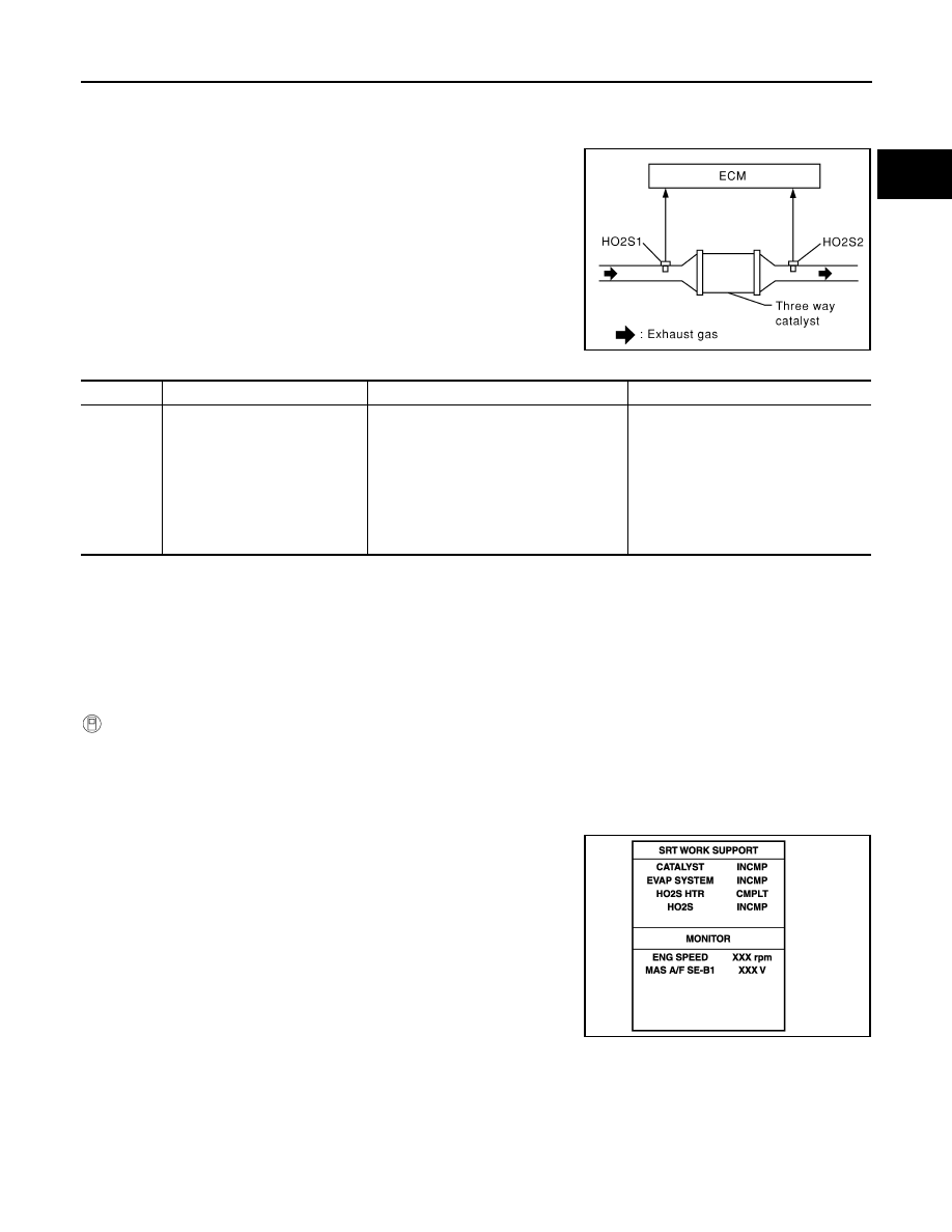
On Board Diagnosis Logic

UBS00D74

The ECM monitors the switching frequency ratio of heated oxygen
sensor 1 and 2.
A three way catalyst (manifold) with high oxygen storage capacity
will indicate a low switching frequency of heated oxygen sensor 2.
As oxygen storage capacity decreases, the heated oxygen sensor 2
switching frequency will increase.
When the frequency ratio of heated oxygen sensors 1 and 2
approaches a specified limit value, the three way catalyst (manifold)
malfunction is diagnosed.

DTC Confirmation Procedure

UBS00D75

NOTE:
If “DTC Confirmation Procedure” has been previously conducted, always turn ignition switch OFF and wait at
least 5 seconds before conducting the next test.
TESTING CONDITION:

Open engine hood before conducting following procedure.

Do not hold engine speed more than specified minutes below.

 With CONSULT-II

1.

Start engine and warm it up to the normal operating temperature.

2.

Turn ignition switch OFF and wait at least 5 seconds.

3.

Start engine and keep the engine speed between 3,500 and 4,000 rpm for at least 1 minute under no load.

4.

Let engine idle for 1 minute.

5.

Select “DTC & SRT CONFIRMATION” then “SRT WORK SUP-
PORT” mode with CONSULT-II.

6.

Rev engine up to 2,000 to 3,000 rpm and hold it for 3 consecu-
tive minutes then release the accelerator pedal completely.
If “INCMP” of “CATALYST” changed to “COMPLT”, go to step 9

7.

Wait 5 seconds at idle.

PBIB0067E

DTC No.

Trouble diagnosis name

DTC detecting condition

Possible Cause

P0420

Catalyst system efficiency below 
threshold

Three way catalyst (manifold) does not 
operate properly.

Three way catalyst (manifold) does not 
have enough oxygen storage capacity.

Three way catalyst (manifold)

Exhaust tube

Intake air leaks

Fuel injector

Injector leaks

Spark plug

Improper ignition timing

PBIB0822E

EC-300

[KA24DE]

DTC P0420 THREE WAY CATALYST FUNCTION

8.

Rev engine up to 2,000 to 3,000 rpm and maintain it until
“INCMP” of “CATALYST” changes to “CMPLT” (It will take
approximately 5 minutes).
If not “CMPLT”, perform the following.

a.

Turn ignition switch OFF and leave the vehicle in a cool place
(soak the vehicle).

b.

Turn ignition switch ON and select 

″COOLAN TEMP/S″ in

″DATA MONITOR″ mode with CONSULT-II.

c.

Start engine and warm it up while monitoring 

″COOLAN TEMP/

S

″ indication on CONSULT-II.

d.

When 

″COOLAN TEMP/S″ indication reaches to 70°C (158°F),

go to step 3.

9.

Select “SELF-DIAG RESULTS” mode with CONSULT-II.

10. Confirm that the 1st trip DTC is not detected.

If the 1st trip DTC is detected, go to 

EC-301, "Diagnostic Proce-

dure"

 .

Overall Function Check

UBS00D76

Use this procedure to check the overall function of the three way catalyst. During this check, a 1st trip DTC
might not be confirmed.

 WITH GST

1.

Start engine and warm it up to the normal operating temperature.

2.

Turn ignition switch OFF and wait at least 5 seconds.

3.

Start engine and keep the engine speed between 3,500 and 4,000 rpm for 1 minute under no load.

4.

Let engine idle for 1 minute.

5.

Set voltmeters probes between ECM terminals 50 (Heated oxy-
gen sensor 1 signal), 56 (Heated oxygen sensor 2 signal) and
engine ground.

6.

Keep engine speed at 2,000 rpm constant under no load.

7.

Make sure that the voltage switching frequency (high & low)
between ECM terminal 56 and engine ground is much less than
that of ECM terminal 50 and engine ground.
Switching frequency ratio = A/B
A: Heated oxygen sensor 2 voltage switching frequency
B: Heated oxygen sensor 1 voltage switching frequency
This ratio should be less than 0.75.
If the ratio is greater than above, it means three way catalyst
(manifold) does not operate properly.
Go to 

EC-301, "Diagnostic Procedure"

 .

PBIB0823E

SEF013Y

SEF535Z

AEC876A

DTC P0420 THREE WAY CATALYST FUNCTION

EC-301

[KA24DE]

C

D

E

F

G

H

I

J

K

L

M

A

EC

NOTE:
If the voltage at terminal 50 does not switch periodically more than 5 times within 10 seconds at step 4,
perform trouble diagnosis for DTC P0133 first. (See 

EC-192

 .)

Diagnostic Procedure

UBS00D77

1. 

CHECK EXHAUST SYSTEM

Visually check exhaust tubes and muffler for dent.
OK or NG

OK

>> GO TO 2.

NG

>> Repair or replace.

2. 

CHECK EXHAUST GAS LEAK

1.

Start engine and run it at idle.

2.

Listen for an exhaust gas leak before three way catalyst (manifold).

OK or NG

OK

>> GO TO 3.

NG

>> Repair or replace.

3. 

CHECK INTAKE AIR LEAK

Listen for an intake air leak after the mass air flow sensor.

OK or NG

OK

>> GO TO 4.

NG

>> Repair or replace.

4. 

CHECK IGNITION TIMING

1.

Check the following items. Refer to 

EC-74, "Basic Inspection"

 .

OK or NG

OK

>> GO TO 5.

NG

>> Adjust ignition timing.

SEC502D

Items

Specifications

Ignition timing

20

° ± 2° BTDC

Base idle speed

750 

± 50 rpm (in P or N position)

Closed throttle position switch idle 
position adjustment

Feeler gauge thickness and switch condition
0.1 mm (0.004 in): ON
0.3 mm (0.012 in): OFF

Target idle speed

800 

± 50 rpm (in P or N position)

EC-302

[KA24DE]

DTC P0420 THREE WAY CATALYST FUNCTION

5. 

CHECK INJECTORS

1.

Refer to Wiring Diagram for Injectors, 

EC-540

 .

2.

Stop engine and then turn ignition switch ON.

3.

Check voltage between ECM terminals 102, 104, 109 and 111
and ground with CONSULT-II or tester.
Battery voltage should exist.

OK or NG

OK

>> GO TO 6.

NG

>> Perform 

EC-301, "Diagnostic Procedure"

 .

6. 

CHECK IGNITION SPARK

1.

Disconnect ignition wire from spark plug.

2.

Connect a known good spark plug to the ignition wire.

3.

Place end of spark plug against a suitable ground and crank engine.

4.

Check for spark.

OK or NG

OK

>> GO TO 8.

NG

>> GO TO 7.

7. 

CHECK IGNITION WIRES

1.

Inspect wires for cracks, damage, burned terminals and for improper fit.

2.

Measure the resistance of wires to their distributor cap terminal.
Move each wire while testing to check for intermittent breaks.

If the resistance exceeds the above specification, inspect igni-
tion wire to distributor cap connection. Clean connection or
replace the ignition wire with a new one.

OK or NG

OK

>> Check ignition coil, power transistor and their circuits.

Refer to 

EC-532, "IGNITION SIGNAL"

 .

NG

>> Replace.

LEC041A

SEF282G

Resistance

: 13.6 - 18.4 k

/m (4.15 - 

5.61 k

/ft) at 25°C (77°F)

SEF174P


Content   ..  297  298  299  300   ..