Nissan Frontier D22. Manual - part 73


  Index      Nissan     Nissan Frontier D22 Pickup (1998-2004 year) - Service and Repair Manual


Search            


Content   ..  71  72  73  74   ..


Nissan Frontier D22. Manual - part 73


DTC P0720 VEHICLE SPEED SENSOR·A/T (REVOLUTION SENSOR)

AT-261

[RE4R01A]

D

E

F

G

H

I

J

K

L

M

A

B

AT

DTC P0720 VEHICLE SPEED SENSOR·A/T (REVOLUTION SENSOR)

PFP:32702

Description

ECS007MC

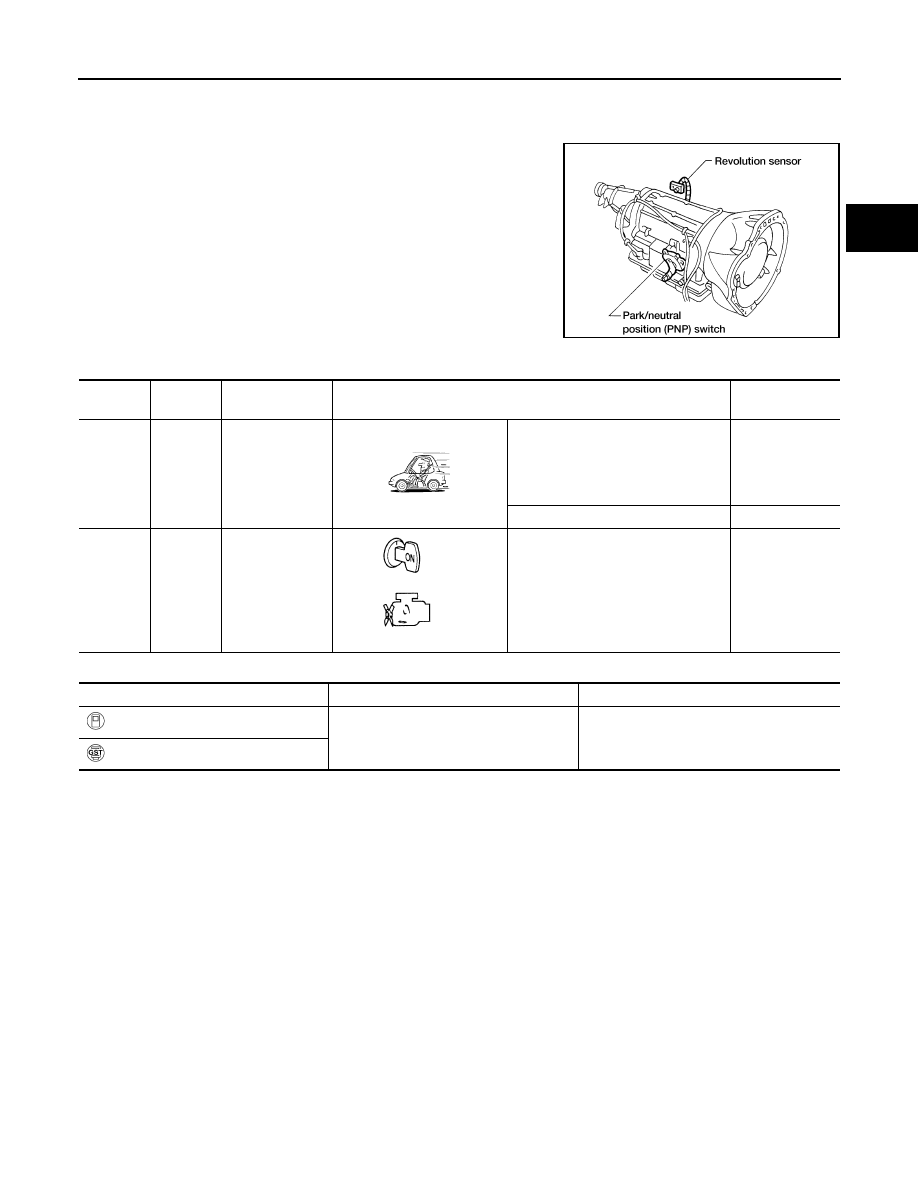
The revolution sensor detects the revolution of the output shaft park-
ing pawl lock gear and emits a pulse signal. The pulse signal is sent
to the TCM which converts it into vehicle speed.

TCM TERMINALS AND REFERENCE VALUE

Remarks: Specification data are reference values.

ON BOARD DIAGNOSIS LOGIC

DIAGNOSTIC TROUBLE CODE (DTC) CONFIRMATION PROCEDURE

CAUTION:

Always drive vehicle at a safe speed.

Be careful not to rev engine into the red zone on the tachometer.

NOTE:
If “DIAGNOSTIC TROUBLE CODE CONFIRMATION PROCEDURE” has been previously conducted,
always turn ignition switch OFF and wait at least 5 seconds before conducting the next test.
After the repair, perform the following procedure to confirm the malfunction is eliminated.

AAT478A

Terminal 

No.

Wire color

Item

Condition

Judgement stan-

dard (Approx.)

29

Y

Revolution sen-
sor
(Measure in AC 
range)

When vehicle cruises at 30 km/h (19 
MPH).

1V or more
Voltage rises 
gradually in 
response to vehi-
cle speed.

When vehicle parks.

0V

42

BR

Throttle position 
sensor
(Ground)

0V

Diagnostic trouble code

Malfunction is detected when ...

Check item (Possible cause)

: VEH SPD SEN/CIR AT

TCM does not receive the proper voltage 
signal from the sensor.

Harness or connectors
(The sensor circuit is open or shorted)

Revolution sensor

: P0720

AT-262

[RE4R01A]

DTC P0720 VEHICLE SPEED SENSOR·A/T (REVOLUTION SENSOR)

 With CONSULT-II

1.

Turn ignition switch ON and select “DATA MONITOR” mode for
“A/T” with CONSULT-II.

2.

Drive vehicle and check for an increase of “VHCL/S SE·MTR”
value.
If the check result is NG, go to 

AT-264, "Diagnostic Procedure"

 .

If the check result is OK, go to following step.

3.

Select “DATA MONITOR” mode for “ENGINE” with CONSULT-II.

4.

Start engine and maintain the following conditions for at least 5
consecutive seconds.
VHCL SPEED SE: 30 km/h (19 MPH) or more
THRTL POS SEN: More than 1.2V

Selector lever: D position (O/D ON)
Driving condition: Driving the vehicle uphill (increased
engine load) will help maintain the driving conditions
required for this test.
If the check result is NG, go to 

AT-264, "Diagnostic Procedure"

 .

If the check result is OK, go to following step.

5.

Maintain the following conditions for at least 5 consecutive sec-
onds.
CMPS·RPM (REF): 3,500 rpm or more
THRTL POS SEN: More than 1.2V
Selector lever: D position (O/D ON)
Driving condition: Driving the vehicle uphill (increased
engine load) will help maintain the driving conditions required for this test.

 With GST

Follow the procedure “With CONSULT-II”.

SAT014K

SAT971J

SEF949Y

DTC P0720 VEHICLE SPEED SENSOR·A/T (REVOLUTION SENSOR)

AT-263

[RE4R01A]

D

E

F

G

H

I

J

K

L

M

A

B

AT

Wiring Diagram — AT — VSSA/T

ECS007MD

WCWA0148E

AT-264

[RE4R01A]

DTC P0720 VEHICLE SPEED SENSOR·A/T (REVOLUTION SENSOR)

Diagnostic Procedure

ECS007ME

1. 

CHECK REVOLUTION SENSOR

Refer to 

AT-265, "Component Inspection"

 .

OK or NG

OK

>> GO TO 2.

NG

>> Repair or replace revolution sensor.

2. 

CHECK INPUT SIGNAL

With CONSULT-II

1.

Start engine.

2.

Select “TCM INPUT SIGNALS” in “DATA MONITOR” mode for “A/T” with CONSULT-II.

3.

Read out the value of “VHCL/S SE·A/T” while driving.
Check the value changes according to driving speed.

 Without CONSULT-II

1.

Start engine.

2.

Check voltage between TCM harness connector M78 terminal 29 (Y) and ground while driving.
(Measure with AC range)

OK or NG

OK

>> GO TO 3.

NG

>> Check the following items:

Harness for short or open between TCM and revolution sensor (Main harness)

Harness for short or open between revolution sensor harness connector E73 and ECM harness
connector M78

Ground circuit for ECM
Refer to 

AT-246, "TROUBLE DIAGNOSIS FOR POWER SUPPLY"

 .

SAT614J

Voltage

At 0 km/h (0 MPH)

: 0V

At 30 km/h (19 MPH)

: 1V or more

(Voltage rises gradually 
in response to vehicle 
speed.)

LCIA0290E


Content   ..  71  72  73  74   ..