Nissan March K13. Manual - part 383


  Index      Nissan     Nissan March K13 - Service and Repair Manual)


Search            


Content   ..  381  382  383  384   ..


Nissan March K13. Manual - part 383


HAC-66

< DTC/CIRCUIT DIAGNOSIS >

[AUTOMATIC AIR CONDITIONER]

POWER SUPPLY AND GROUND CIRCUIT

2.

Disconnect the blower motor relay from the fuse block (J/B). Refer to 

XX-XX, "*****"

.

3.

Turn the ignition switch ON.

4.

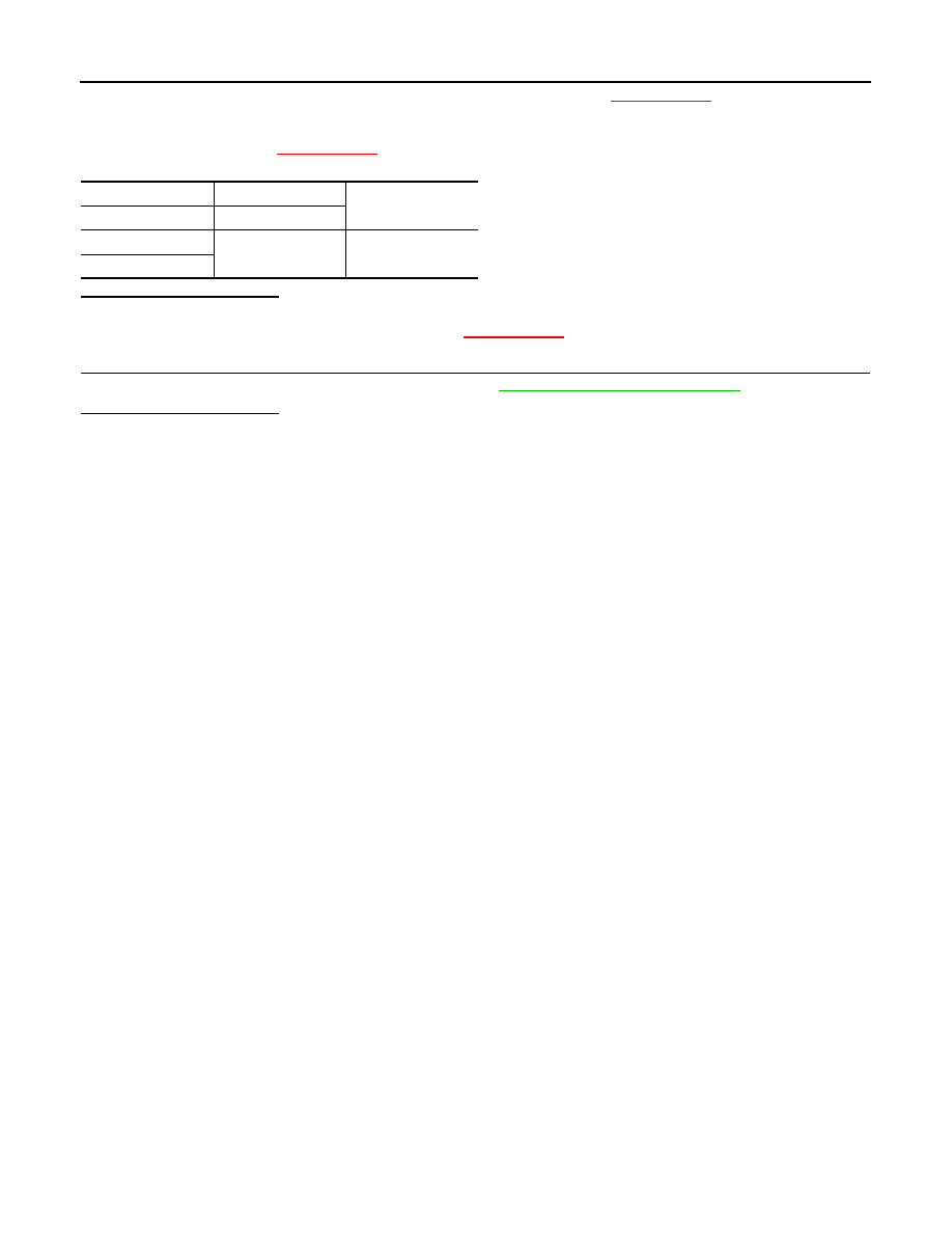
Check voltage between the ground and the connector on the fuse block side where blower motor relay
was installed. Refer to 

XX-XX, "*****"

.

Is inspection result normal?

YES

>> GO TO 6.

NO

>> Repair the power supply circuit. Refer to 

XX-XX, "*****"

.

6.

CHECK BLOWER MOTOR RELAY

Perform the blower motor component inspection. Refer to 

HAC-58, "Component Inspection"

.

Is inspection result normal?

YES

>> Repair the harness or connector between blower motor relay and A/C auto amp.

NO

>> Replace blower motor relay.

(+)

(

)

Voltage

(Approx.)

Fuse block (J/B)

1

Ground

Battery voltage

3

A/C AUTO AMP.

HAC-67

< DTC/CIRCUIT DIAGNOSIS >

[AUTOMATIC AIR CONDITIONER]

C

D

E

F

G

H

J

K

L

M

A

B

HAC

N

O

P

A/C AUTO AMP.

Component Function Check

INFOID:0000000006024059

1.

CHECK OPERATION

1.

Confirm that “AUTO” is indicated on the display by operating the AUTO switch. 

2.

Operate the temperature control switch. Check that the fan speed or discharge air changes (the discharge
air temperature or fan speed varies depending on the ambient temperature, in-vehicle temperature, and
set temperature). 

Does it operate normally?

YES

>> INSPECTION END

NO

>> Perform the diagnosis for the A/C auto amp. Refer to 

HAC-67, "Diagnosis Procedure"

.

Diagnosis Procedure

INFOID:0000000006024060

1.

CHECK A/C AUTO AMP. POWER SUPPLY CIRCUIT AND GROUND CIRCUIT

Check A/C auto amp. power supply circuit and ground circuit. Refer to 

HAC-65, "A/C AUTO AMP. : Diagnosis

Procedure"

.

Is the inspection result normal?

YES

>> INSPECTION END

NO

>> Repair or replace parts depending on the inspection results.

HAC-68

< SYMPTOM DIAGNOSIS >

[AUTOMATIC AIR CONDITIONER]

AUTOMATIC AIR CONDITIONER SYSTEM

SYMPTOM DIAGNOSIS

AUTOMATIC AIR CONDITIONER SYSTEM

Diagnosis Chart By Symptom

INFOID:0000000006024072

CAUTION:

Perform the self-diagnoses with on board diagnosis and CONSULT-III before performing the symptom
diagnosis. If any malfunction result or DTC is detected, perform the corresponding diagnosis.

Symptom

Corresponding malfunction part

Check item/Reference

A/C system does not activate.

• Power supply circuit of A/C system
• A/C control (built-in A/C auto amp.)

HAC-65, "A/C AUTO AMP. : Di-
agnosis Procedure"

A/C system cannot be controlled.

Blower motor operation is malfunctioning.

• Blower  motor
• Power supply system of blower mo-

tor

• The circuit between blower motor 

and A/C auto amp.

• A/C auto amp.

HAC-57, "Diagnosis Procedure"


Magnet clutch does not operate. 

• Magnet clutch
• The circuit between magnet clutch 

and IPDM E/R

• IPDM E/R (A/C relay)
• The circuit between ECM and refrig-

erant pressure sensor

• Refrigerant pressure sensor
• CAN communication line
• A/C auto amp.

HAC-60, "Diagnosis Procedure"

• Insufficient cooling
• No cool air comes out. (Air flow volume is normal.)

• Magnet clutch control system
• Drive belt slipping
• Cooler cycle
• Air leakage from each duct
• Temperature setting trimmer

HAC-69, "Diagnosis Procedure"

• Insufficient heating
• No warm air comes out. (Air flow volume is normal.)

• Engine cooling system
• Heater hose
• Heater core
• Air leakage from each duct
• Temperature setting trimmer

HAC-71, "Diagnosis Procedure"

Noise is heard when the A/C 
system operates.

During compressor op-
eration

Cooler cycle 

XX-XX, "*****"

During blower motor op-
eration

• Mixing any foreign object in blower 

motor

• Blower motor fan breakage
• Blower motor rotation inferiority

HAC-58, "Component Inspec-
tion"

• Memory function dose not operates.
• Setting temperature dose not memorize.

• Power supply system of A/C auto 

amp.

• A/C auto amp.

HAC-74, "Inspection Proce-
dure"

INSUFFICIENT COOLING

HAC-69

< SYMPTOM DIAGNOSIS >

[AUTOMATIC AIR CONDITIONER]

C

D

E

F

G

H

J

K

L

M

A

B

HAC

N

O

P

INSUFFICIENT COOLING

Description

INFOID:0000000006024073

Symptom

• Insufficient cooling
• No cool air comes out. (Air flow volume is normal.)

Diagnosis Procedure

INFOID:0000000006024074

CAUTION:

Perform the self-diagnoses with on board diagnosis and CONSULT-III before performing symptom
diagnosis. If any malfunction result or DTC is detected, perform the corresponding diagnosis.

1.

CHECK MAGNET CLUTCH OPERATION

1.

Turn the ignition switch ON.

2.

Operate the fan control switch.

3.

Press the A/C switch.

4.

Check that the indicator of the A/C switch turns ON. Check visually and by sound that the compressor
operates.

5.

Press the A/C switch again.

6.

Check that the indicator of the A/C switch turns OFF. Check that the compressor stops.

Is the inspection result normal?

YES

>> GO TO 2.

NO

>> Perform the diagnosis of “COMPRESSOR DOSE NOT OPERATE” in “SYMPTOM DIAGNOSIS”.

Refer to 

HAC-72, "Diagnosis Procedure"

.

2.

CHECK DRIVE BELT

Check tension of the drive belt. Refer to 

XX-XX, "*****"

.

Is the inspection result normal?

YES

>> GO TO 3.

NO

>> Adjust or replace drive belt depending on the inspection results.

3.

CHECK REFRIGERANT CYCLE PRESSURE

Connect the recovery/recycling recharging equipment to the vehicle and perform the pressure inspection with
the gauge. Refer to 

XX-XX, "*****"

.

Is the inspection result normal?

YES

>> GO TO 4.

NO

>> Repair or replace the parts depending on the inspection results.

4.

CHECK AIR LEAKAGE FROM EACH DUCT

Check duct and nozzle, etc. of the air conditioner system for leakage.
Is the inspection result normal?

YES

>> GO TO 5.

NO

>> Repair or replace parts depending on the inspection results.

5.

CHECK AMBIENT TEMPERATURE DISPLAY

Check that there is not much difference between actual ambient temperature and indicated temperature on
information display in combination meter. 
NOTE:
Actual ambient temperature is sensor recognition temperature of on board self-diagnosis STEP-5.

Is the inspection result normal?

YES

>> GO TO 6.

NO

>> Perform the diagnosis for the A/C auto amp. connection recognition signal. Refer to 

XX-XX,

"*****"

.

6.

CHECK SETTING OF TEMPERATURE SETTING TRIMMER

1.

Check the setting value of temperature setting trimmer. Refer to 

HAC-41, "Temperature Setting Trimmer"


Content   ..  381  382  383  384   ..