Nissan March K13. Manual - part 105
HOOD LOCK
DLK-131
< REMOVAL AND INSTALLATION >
[WITH INTELLIGENT KEY SYSTEM]
C
D
E
F
G
H
I
J
L
M
A
B
DLK
N
O
P
HOOD LOCK
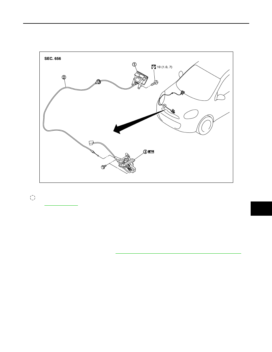
Exploded View
INFOID:0000000005949006
Removal and Installation
INFOID:0000000005949007
REMOVAL
1.
Remove remove hood lock assembly mounting bolts, and then remove hood lock assembly.
2.
Disconnect hood lock cable from hood lock assembly.
3.
Remove hood lock cable clip.
4.
Remove fender protector (RH). Refer to
EXT-17, "FENDER PROTECTOR : Removal and Installation"
.
5.
Remove hood lock opener lever.
6.
Disconnect hood lock cable from hood lock opener lever.
7.
Remove grommet on the lower dash, and pull the hood lock control cable toward the passenger compart-
ment.
CAUTION:
While pulling, never to damage (peeling) the outside of hood lock control cable.
INSTALLATION
Note the following items, and install in the reverse order of removal.
CAUTION:
• Never to bend cable too much, keeping the radius 100 mm (3.937 in) or more.
1.
Hood lock opener lever
2.
Hood lock control cable
3.
Hood lock assembly
: Clip
Refer to
JMKIA5352GB