Index Nissan Nissan Almera Tino V10 - Service Manual (2003 year)
Search
Content .. 379 380 381 382 ..
Nissan Almera Tino V10. Manual - part 381
EC-350
[QG (WITH EURO-OBD)]
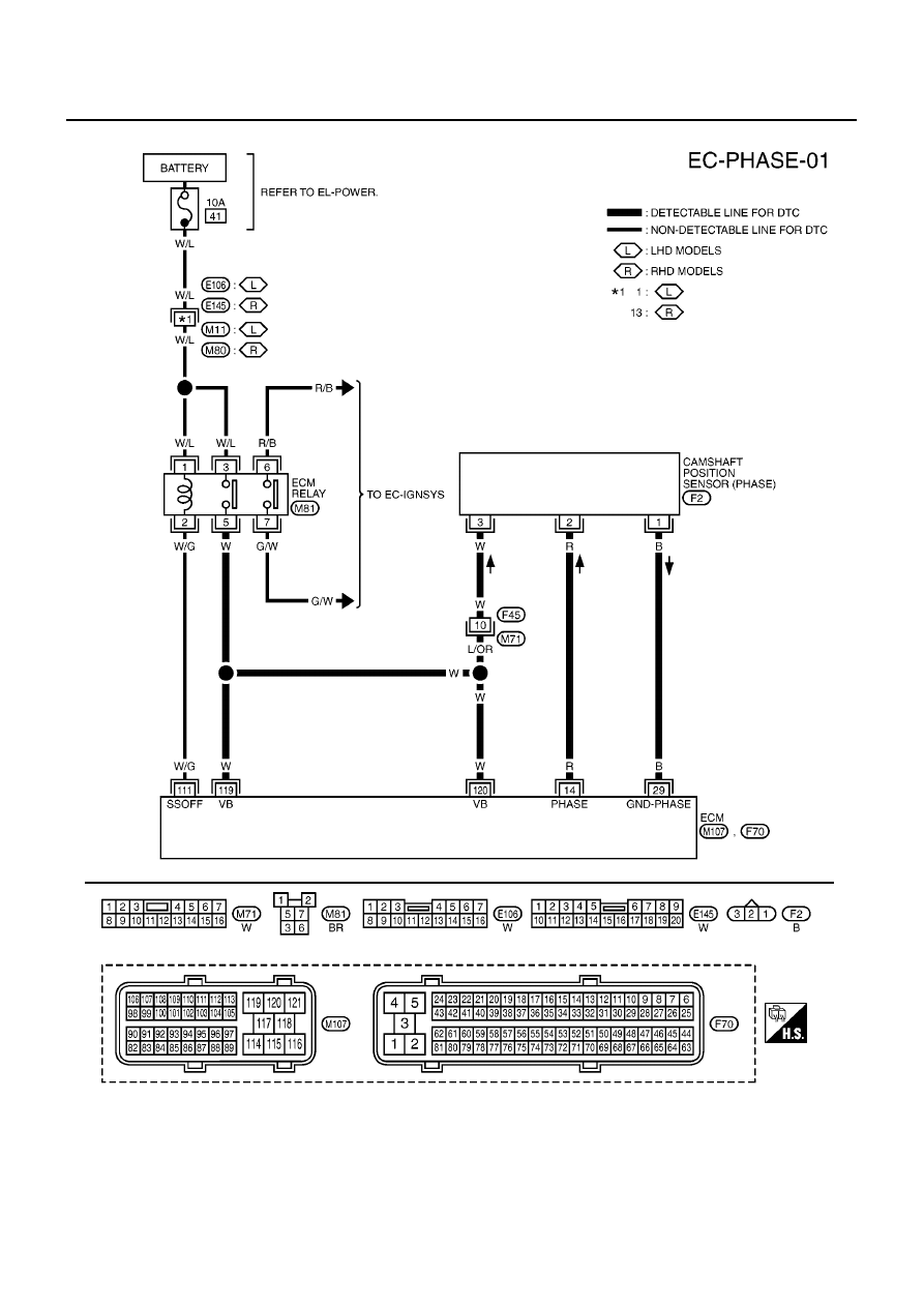
DTC P0340 CMP SENSOR (PHASE)
Wiring Diagram
EBS00QNK
YEC458A