Nissan Pathfinder. Manual - part 742
PUSH-BUTTON IGNITION SWITCH ILLUMINATION CIRCUIT
INL-55
< DTC/CIRCUIT DIAGNOSIS >
C
D
E
F
G
H
I
J
K
M
A
B
INL
N
O
P
PUSH-BUTTON IGNITION SWITCH ILLUMINATION CIRCUIT
Description
INFOID:0000000009175449
Provides the power supply and the ground to control the push-button ignition switch illumination.
Component Function Check
INFOID:0000000009175450
1.
CHECK PUSH-BUTTON IGNITION SWITCH ILLUMINATION OPERATION
CONSULT
1. Turn the ignition switch ON.
2. Select ENGINE SW ILLUMI of BCM (INTELLIGENT KEY) active test item.
3. While operating the test items, check that the push-button ignition switch illumination turns ON/OFF.
Does the push-button ignition switch illumination turn ON/OFF?
YES
>> Push-button ignition switch illumination circuit is normal.
NO
>> Refer to
.
Diagnosis Procedure
INFOID:0000000009175451
Regarding Wiring Diagram information, refer to
.
1.
CHECK PUSH-BUTTON IGNITION SWITCH ILLUMINATION OPERATION
CONSULT
1. Turn the ignition switch ON.
2. Select ENGINE SW ILLUMI of BCM (INTELLIGENT KEY) active test item.
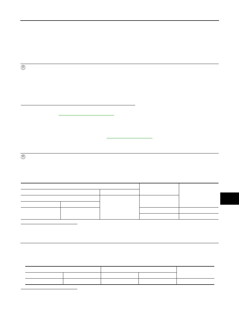
3. While operating the test item, check voltage between push-button ignition switch connector M17 terminal
5 and ground.
Is the inspection result normal?
YES
>> GO TO 4.
NO
>> GO TO 2.
2.
CHECK PUSH-BUTTON IGNITION SWITCH ILLUMINATION POWER SUPPLY OPEN CIRCUIT
1. Turn the ignition switch OFF.
2. Disconnect BCM harness connector M19 and the push-button ignition switch harness connector M17.
3. Check continuity between BCM harness connector M19 terminal 48 and the push-button ignition switch
harness connector M17 terminal 5.
Is the inspection result normal?
YES
>> GO TO 3.
On
: Push-button ignition switch illumination ON
Off
: Push-button ignition switch illumination OFF
Terminals
Test item
Voltage
(Approx.)
(+)
(-)
Push-button ignition switch
Ground
ENGINE SW ILLUMI
Connector
Terminal
M17
5
ON
5 V
OFF
0 V
BCM
Push-button ignition switch
Continuity
Connector
Terminal
Connector
Terminal
M19
48
M17
5
Yes