Nissan Pathfinder. Manual - part 628
BACK DOOR OUTER FINISHER
EXT-43
< REMOVAL AND INSTALLATION >
C
D
E
F
G
H
I
J
L
M
A
B
EXT
N
O
P
BACK DOOR OUTER FINISHER
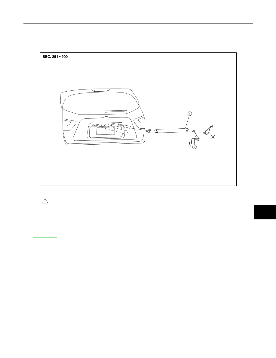
Exploded View
INFOID:0000000009176361
Removal and Installation
INFOID:0000000009176362
REMOVAL
1. Remove the back door lower finisher. Refer to
INT-35, "BACK DOOR LOWER FINISHER : Removal and
.
2. Disconnect the harness connectors from rear view camera and back door opener switch.
3. Remove the back door outer finisher nuts.
4. Release the clips, then remove the back door outer finisher.
5. Remove the following parts (if necessary) after removing back door outer finisher.
• Rear view camera
• Back door opener switch
• License plate lamp
INSTALLATION
Installation is in the reverse order of removal.
1.
Back door outer finisher
2.
Rear camera
3.
Back door opener request switch
Clip
AWKIA2640ZZ