Nissan Pathfinder. Manual - part 442
EC-74
< ECU DIAGNOSIS INFORMATION >
[VQ35DE]
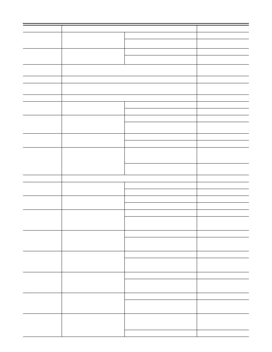
ECM
TP SEN 1-B1
• Ignition switch: ON
(Engine stopped)
• Selector lever: D position
Accelerator pedal: Fully released
More than 0.36 V
Accelerator pedal: Fully depressed
Less than 4.75 V
TP SEN 2-B1*
1
• Ignition switch: ON
(Engine stopped)
• Selector lever: D position
Accelerator pedal: Fully released
More than 0.36 V
Accelerator pedal: Fully depressed
Less than 4.75 V
FUEL T/TMP SE
Ignition switch: ON
Indicates fuel tank tempera-
ture
EVAP SYS PRES
Ignition switch: ON
Approx. 1.8 - 4.8 V
FUEL LEVEL SE
Ignition switch: ON
Depending on fuel level of
fuel tank
START SIGNAL
Ignition switch: ON
→ START → ON
Off
→ On → Off
CLSD THL POS
Ignition switch: ON
(Engine stopped)
Accelerator pedal: Fully released
On
Accelerator pedal: Slightly depressed
Off
AIR COND SIG
Engine: After warming up, idle the
engine
Air conditioner switch: OFF
Off
Air conditioner switch: ON
(Compressor operates.)
On
PW/ST SIGNAL
Engine: After warming up, idle the
engine
Steering wheel: Not being turned
Off
Steering wheel: Being turned
On
LOAD SIGNAL
Ignition switch: ON
Rear window defogger switch: ON
and/or
Lighting switch: 2nd position
On
Rear window defogger switch and lighting
switch: OFF
Off
IGNITION SW
Ignition switch: ON
→ OFF → ON
On
→ Off → On
HEATER FAN SW
Engine: After warming up, idle the
engine
Heater fan switch: ON
On
Heater fan switch: OFF
Off
BRAKE SW
Ignition switch: ON
Brake pedal: Fully released
Off
Brake pedal: Slightly depressed
On
INJ PULSE-B1
• Engine: After warming up
• Selector lever: P or N position
• Air conditioner switch: OFF
• No load
Idle
2.0 - 3.0 msec
2,000 rpm
1.9 - 2.9 msec
INJ PULSE-B2
• Engine: After warming up
• Selector lever: P or N position
• Air conditioner switch: OFF
• No load
Idle
2.0 - 3.0 msec
2,000 rpm
1.9 - 2.9 msec
IGN TIMING
• Engine: After warming up
• Selector lever: P or N position
• Air conditioner switch: OFF
• No load
Idle
7 - 17
°BTDC
2,000 rpm
25 - 45
°BTDC
CAL/LD VALUE
• Engine: After warming up
• Selector lever: P or N position
• Air conditioner switch: OFF
• No load
Idle
5 - 35%
2,500 rpm
5 - 35%
MASS AIRFLOW
• Engine: After warming up
• Selector lever: P or N position
• Air conditioner switch: OFF
• No load
Idle
2.0 - 6.0 g/s
2,500 rpm
7.0 - 20.0 g/s
PURG VOL C/V
• Engine: After warming up
• Selector lever: P or N position
• Air conditioner switch: OFF
• No load
Idle
(Accelerator pedal: Not depressed even
slightly, after engine starting.)
0%
2,000 rpm
—
Monitor Item
Condition
Values/Status