Nissan Teana J32. Manual - part 846
MWI
METER CONTROL SWITCH
MWI-127
< ON-VEHICLE REPAIR >
C
D
E
F
G
H
I
J
K
L
M
B
A
O
P
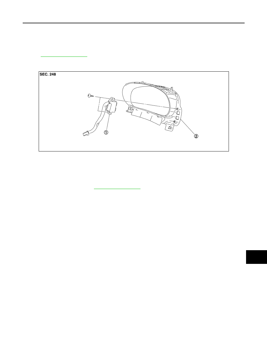
METER CONTROL SWITCH
Exploded View
INFOID:0000000003792624
REMOVAL
.
DISASSEMBLY
Removal and Installation
INFOID:0000000003792625
REMOVAL
1.
Remove cluster lid A. Refer to
2.
Remove screws and remove meter control switch from cluster lid A.
INSTALLATION
Install in the reverse order of removal.
1.
Meter control switch
2.
Cluster lid A
JPNIA1024ZZ