Nissan Teana J32. Manual - part 705


  Index      Nissan     Nissan Teana J32 (2008 year) - Service and Repair Manual


Search            


Content   ..  703  704  705  706   ..


Nissan Teana J32. Manual - part 705


B263D B263E, B263F, B2656 INTAKE DOOR MOTOR

HAC-189

< COMPONENT DIAGNOSIS >

[WITH 7 INCH DISPLAY]

C

D

E

F

G

H

J

K

L

M

A

B

HAC

N

O

P

YES

>> INSPECTION END

NO

>> Check intake door motor installation, and repair or replace the malfunctioning parts.

3.

FUNCTION INSPECTION (WITH INTELLIGENT AIR CONDITIONER SYSTEM)

1.

Press intake switch.

2.

The intake switch indicator is turned ON. (REC position)

3.

Listen for intake door position change (Slight change of blower sound can be heard.).

4.

Press intake switch again.

5.

The intake switch indicator is turned ON. (FRE position)

6.

Listen for intake door position change (Slight change of blower sound can be heard.).

Does it operate normally?

YES

>> INSPECTION END

NO

>> Check intake door motor installation, and repair or replace the malfunctioning parts.

Diagnosis Procedure

INFOID:0000000003884771

1.

CHECK POWER SUPPLY FOR INTAKE DOOR MOTOR

Check voltage between intake door motor harness connector and ground.

Is the inspection result normal?

YES

>> GO TO 2.

NO

>> Repair harness or connector.

2.

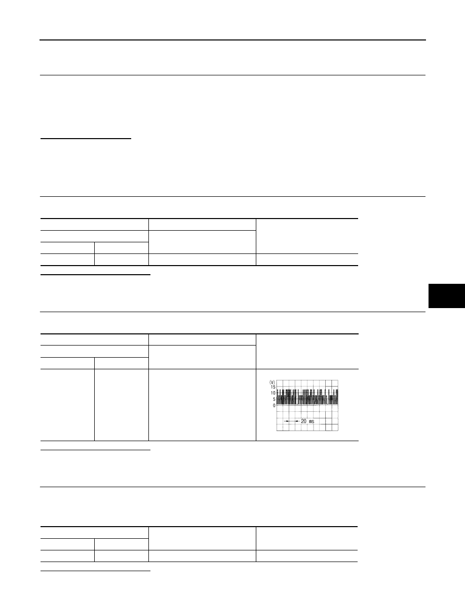
CHECK SIGNAL FOR INTAKE DOOR MOTOR

Confirm A/C LAN signal between intake door motor harness connector and ground using an oscilloscope.

Is the inspection result normal?

YES

>> GO TO 3.

NO

>> Repair harness or connector.

3.

CHECK INTAKE DOOR MOTOR GROUND CIRCUIT

1.

Turn ignition switch OFF.

2.

Disconnect intake door motor connector.

3.

Check continuity between intake door motor harness connector and ground.

Is the inspection result normal?

(+)

(

)

Voltage

Intake door motor

Connector

Terminal

M304

1

Ground

Battery voltage

(+)

(

)

Voltage

Intake door motor

Connector

Terminal

M304

3

Ground

SJIA1453J

Intake door motor

Continuity

Connector

Terminal

M304

2

Ground

Existed

HAC-190

< COMPONENT DIAGNOSIS >

[WITH 7 INCH DISPLAY]

B263D B263E, B263F, B2656 INTAKE DOOR MOTOR

YES

>> Replace intake door motor.

NO

>> Repair harness or connector.

POWER SUPPLY AND GROUND CIRCUIT

HAC-191

< COMPONENT DIAGNOSIS >

[WITH 7 INCH DISPLAY]

C

D

E

F

G

H

J

K

L

M

A

B

HAC

N

O

P

POWER SUPPLY AND GROUND CIRCUIT

A/C AUTO AMP.

A/C AUTO AMP. : Diagnosis Procedure

INFOID:0000000003941319

1.

CHECK FUSE

Check 10A fuses [Nos. 3, 6 and 19, located in the fuse block (J/B)].
NOTE:
Refer to 

PG-101, "Fuse, Connector and Terminal Arrangement"

.

Is the inspection result normal?

YES

>> GO TO 2.

NO

>> Replace the fuse after repairing the applicable circuit. 

2.

CHECK A/C AUTO AMP. POWER SUPPLY CIRCUIT

1.

Disconnect the A/C auto amp. connector. 

2.

Check voltage between A/C auto amp. harness connector and ground. 

Is the inspection result normal?

YES

>> GO TO 3.

NO

>> Repair the harnesses or connectors.

3.

CHECK A/C AUTO AMP. CIRCUIT CONTINUITY

1.

Turn ignition switch OFF.

2.

Check continuity between A/C auto amp. harness connector and ground. 

Is the inspection result normal?

YES

>> INSPECTION END 

NO

>> Repair the harnesses or connectors.

(+)

(

)

Voltage

A/C auto amp.

Ignition switch position

Connector

Terminal

OFF

ACC

ON

M50

17

Ground

Approx. 0 V

Battery voltage

Battery voltage

20

Approx. 0 V

Approx. 0 V

Battery voltage

40

Battery voltage

Battery voltage

Battery voltage

A/C auto amp.

Continuity

Connector

Terminal

M50

19

Ground

Existed

39

HAC-192

< COMPONENT DIAGNOSIS >

[WITH 7 INCH DISPLAY]

A/C AUTO AMP.

A/C AUTO AMP.

Description

INFOID:0000000003941321

COMPONENT DESCRIPTION

A/C Auto Amp. (Air Conditioner Automatic Amplifier)

The A/C auto amp. (1) has a built-in microcomputer that processes
information sent from various sensors needed for air conditioner
operation. The air mix door motors, the mode door motor, the intake
door motor, the blower motor and the compressor are then con-
trolled.
When the various switches and temperature control dial are oper-
ated, data is input to the A/C auto amp. from the A/C control.

Component Function Check

INFOID:0000000003940728

1.

CHECK OPERATION

1.

Press the AUTO switch, and then check that “AUTO” is shown on the display. 

2.

Operate the temperature control dial (driver side). Check that the fan speed or outlet changes. (The dis-
charge air temperature or fan speed varies depending on the ambient temperature, in-vehicle tempera-
ture, and temperature setting.) 

Does it operate normally?

YES

>> INSPECTION END

NO

>> Perform trouble diagnosis for the A/C system. Refer to 

HAC-192, "Diagnosis Procedure"

.

Diagnosis Procedure

INFOID:0000000003940729

1.

INSPECTION BY FAIL-SAFE FUNCTION

1.

Turn the ignition switch ON.

2.

After approximately 30 seconds, check that the air conditioner is operated by the fail-safe function (the
operation display of air conditioner is not performed). Refer to 

HAC-211, "WITHOUT INTELLIGENT AIR

CONDITIONER SYSTEM : Fail-Safe"

 (WITHOUT INTELLIGENT AIR CONDITIONER SYSTEM) or 

HAC-

223, "WITH INTELLIGENT AIR CONDITIONER SYSTEM : Fail-Safe"

 (WITH INTELLIGENT AIR CONDI-

TIONER SYSTEM).

Is the fail-safe function operated? 

YES

>> GO TO 3.

NO

>> GO TO 2.

2.

CHECK A/C AUTO AMP. POWER SUPPLY CIRCUIT AND GROUND

Check A/C auto amp. power supply circuit and ground circuit. Refer to 

HAC-192, "Diagnosis Procedure"

.

Is the inspection result normal?

YES

>> GO TO 3.

NO

>> Repair or replace parts according to the inspection results.

3.

CHECK PRESET SWITCH

Check the preset switch. Refer to 

AV-164, "Symptom Table"

 (BASE AUDIO AND DISPLAY SYSTEM), 

AV-372,

"Symptom Table"

 (BOSE AUDIO WITHOUT NAVIGATION) or 

AV-640, "Symptom Table"

 (BOSE AUDIO WITH

NAVIGATION). 
Is the inspection result normal?

YES

>> Replace the A/C auto amp. 

NO

>> Repair or replace parts according to the inspection results.

JPIIA0894ZZ


Content   ..  703  704  705  706   ..