Nissan Teana J32. Manual - part 643


  Index      Nissan     Nissan Teana J32 (2008 year) - Service and Repair Manual


Search            


Content   ..  641  642  643  644   ..


Nissan Teana J32. Manual - part 643


GW-26

< ON-VEHICLE REPAIR >

REAR REGULATOR

Install in the reverse order of removal.

Disassembly and Assembly

INFOID:0000000003825391

DISASSEMBLY

Remove power window motor from regulator assembly.

ASSEMBLY

Assemble in the reverse order of disassembly.

Inspection and Adjustment

INFOID:0000000003825392

Inspection after Removal

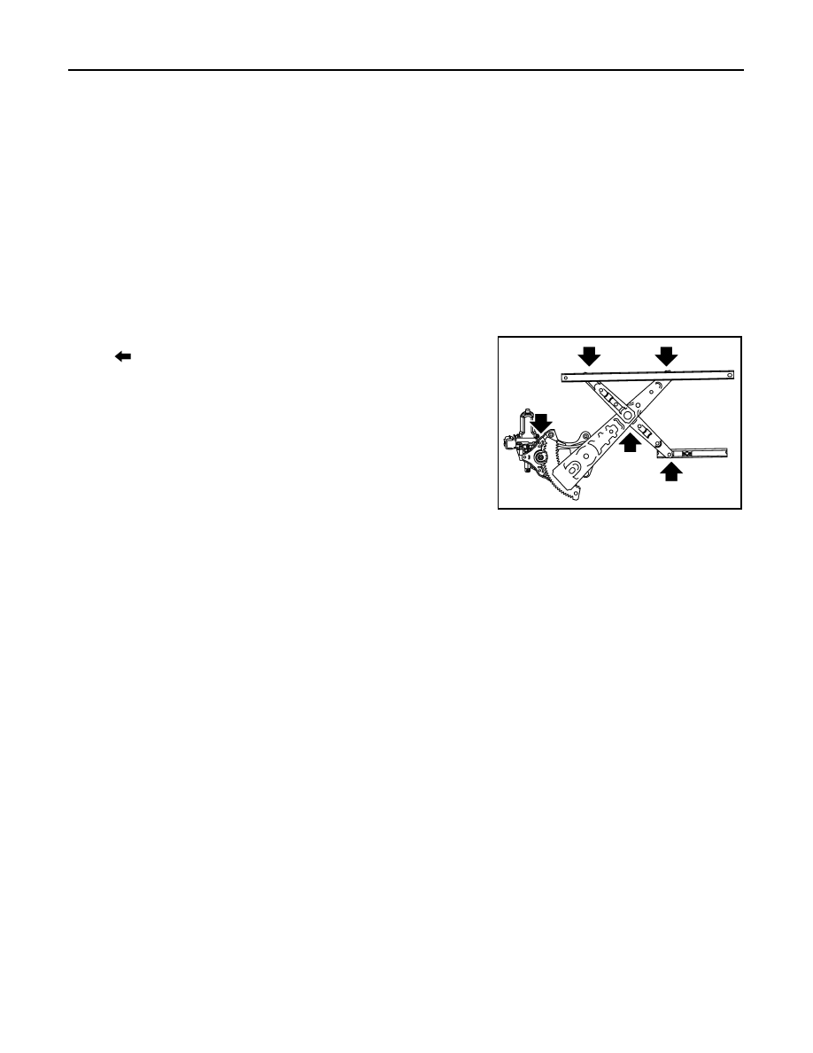
Check the regulator assembly for the following items. Replace or grease it if a malfunction is detected.
• Wire wear
• Regulator deformation
The arrows in the figure show the application points of the multi-purpose grease.

FITTING INSPECTION

• Check that the glass is fit securely into the sash groove.
• Lower the glass slightly [approximately 10 to 20 mm (0.394 to 0.787 in)], and check that the clearance to the

sash is parallel. Loosen the regulator mounting bolts, guide rail mounting bolts, and glass and carrier plate
mounting bolts to correct the glass position if the clearance between the glass and sash is not parallel.

: Grease application point

JMKIA2318ZZ

HA-1

VENTILATION, HEATER & AIR CONDITIONER

C

D

E

F

G

H

J

K

L

M

SECTION 

HA

A

B

HA

N

O

P

CONTENTS

HEATER & AIR CONDITIONING SYSTEM

BASIC INSPECTION  ....................................

3

DIAGNOSIS AND REPAIR WORK FLOW  .........

3

Work Flow  .................................................................

3

FUNCTION DIAGNOSIS ...............................

5

REFRIGERATION SYSTEM  ...............................

5

System Diagram ........................................................

5

System Description  ...................................................

5

Component Parts Location ........................................

6

Component Description .............................................

7

SYMPTOM DIAGNOSIS  ...............................

8

REFRIGERATION SYSTEM SYMPTOMS  ..........

8

Trouble Diagnosis For Unusual Pressure  .................

8

Symptom Table  .........................................................

8

COMPRESSOR SYSTEM SYMPTOMS .............

11

Symptom Table  .......................................................

11

PRECAUTION ..............................................

12

PRECAUTIONS ..................................................

12

Precaution for Supplemental Restraint System 
(SRS) "AIR BAG" and "SEAT BELT PRE-TEN-
SIONER" .................................................................

12

Precaution Necessary for Steering Wheel Rota-
tion after Battery Disconnect  ...................................

12

Precaution for Procedure without Cowl Top Cover 

....

13

Precautions For Xenon Headlamp Service  .............

13

Working with HFC-134a (R-134a)  ...........................

13

General Refrigerant Precaution  ..............................

13

Refrigerant Connection  ...........................................

14

Service Equipment  ..................................................

16

COMPRESSOR  ..................................................

19

General Precautions  ...............................................

19

FLUORESCENT LEAK DETECTOR  .................

20

General Precautions  ...............................................

20

PREPARATION ...........................................

21

PREPARATION .................................................

21

Special Service Tool ................................................

21

Sealant or/and Lubricant  .........................................

23

ON-VEHICLE MAINTENANCE ....................

24

REFRIGERANT .................................................

24

Collection and Charge  .............................................

24

LUBRICANT ......................................................

28

Maintenance of Lubricant Quantity ..........................

28

Lubricant Adjusting Procedure for Components 
Replacement Except Compressor ...........................

28

Lubricant Adjusting Procedure for Compressor 
Replacement ...........................................................

29

REFRIGERATION SYSTEM  .............................

30

Inspection ................................................................

30

Performance Chart  ..................................................

30

Refrigerant Leakages  ..............................................

31

FLUORESCENT LEAK DETECTOR  ................

32

Inspection ................................................................

32

ELECTRICAL LEAK DETECTOR  ....................

33

Inspection ................................................................

33

ON-VEHICLE REPAIR .................................

36

COMPRESSOR .................................................

36

Exploded View .........................................................

36

Removal and Installation  .........................................

36

Inspection ................................................................

37

LOW-PRESSURE FLEXIBLE HOSE ................

38

Exploded View .........................................................

38

Removal and Installation  .........................................

38

HIGH-PRESSURE FLEXIBLE HOSE  ...............

40

Exploded View .........................................................

40

Removal and Installation  .........................................

40

HA-2

LOW-PRESSURE PIPE  .....................................

42

Exploded View  ........................................................

42

Removal and Installation  ........................................

42

HIGH-PRESSURE PIPE  ....................................

44

Exploded View  ........................................................

44

Removal and Installation  ........................................

44

CONDENSER ....................................................

46

Exploded View  ........................................................

46

Removal and Installation  ........................................

46

CONDENSER PIPE ASSEMBLY  ......................

48

Exploded View  ........................................................

48

Removal and Installation  ........................................

48

LIQUID TANK  ....................................................

50

Exploded View  ........................................................

50

Removal and Installation  ........................................

50

REFRIGERANT PRESSURE SENSOR  ............

51

Exploded View  ........................................................

51

Removal and Installation  ........................................

51

EVAPORATOR ..................................................

52

Exploded View  ........................................................

52

Removal and Installation .........................................

53

EVAPORATOR PIPE ASSEMBLY ....................

54

Exploded View  ........................................................

54

Removal and Installation .........................................

55

EXPANSION VALVE  .........................................

57

Exploded View  ........................................................

57

Removal and Installation .........................................

58

SERVICE DATA AND SPECIFICATIONS 
(SDS) ..........................................................

59

SERVICE DATA AND SPECIFICATIONS 
(SDS) .................................................................

59

Compressor ............................................................

59

Lubricant .................................................................

59

Refrigerant ..............................................................

59

Engine Idling Speed ................................................

59

Belt Tension  ............................................................

59

DIAGNOSIS AND REPAIR WORK FLOW

HA-3

< BASIC INSPECTION >

C

D

E

F

G

H

J

K

L

M

A

B

HA

N

O

P

BASIC INSPECTION

DIAGNOSIS AND REPAIR WORK FLOW

Work Flow

INFOID:0000000003795801

OVERALL SEQUENCE

*1: Refer to the following.

HAC-85, "DTC Index"

 (WITHOUT 7 INCH DISPLAY)

HAC-212, "WITHOUT INTELLIGENT AIR CONDITIONER SYSTEM : DTC Index"

 [WITH 7 INCH DISPLAY

(WITHOUT INTELLIGENT AIR CONDITIONER SYSTEM)]

HAC-224, "WITH INTELLIGENT AIR CONDITIONER SYSTEM : DTC Index"

 [WITH 7 INCH DISPLAY

(WITH INTELLIGENT AIR CONDITIONER SYSTEM)]

*2: Refer to the following.

HAC-87, "Diagnosis Chart By Symptom"

 (WITHOUT 7 INCH DISPLAY)

HAC-226, "Diagnosis Chart By Symptom"

 (WITH 7 INCH DISPLAY)

DETAILED FLOW

1.

OBTAIN INFORMATION ABOUT SYMPTOM

Interview the customer to obtain as much information as possible about the conditions and environment under
which the malfunction occurred.

>> GO TO 2.

JSIIA0943GB


Content   ..  641  642  643  644   ..