Nissan Teana J32. Manual - part 610
FRONT DRIVE SHAFT BOOT
FAX-11
< ON-VEHICLE REPAIR >
C
E
F
G
H
I
J
K
L
M
A
B
FAX
N
O
P
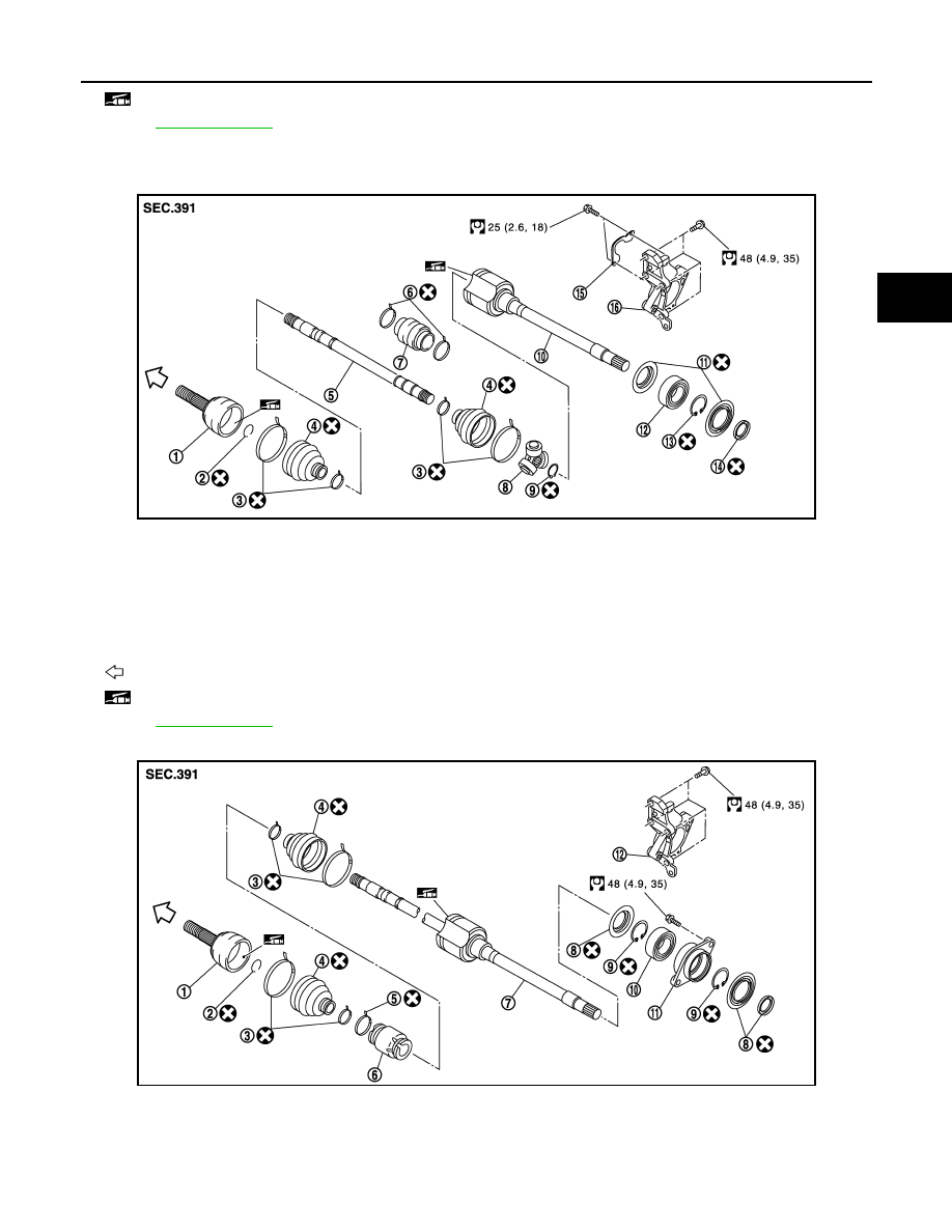
RIGHT SIDE
VQ25DE
VQ35DE
: Fill NISSAN Genuine grease or equivalent.
Refer to
for symbols not described on the above.
JPDIF0184GB
1.
Joint sub-assembly
2.
Circular clip
3.
Boot band
4.
Boot
5.
Shaft
6.
Damper band
7.
Dynamic damper
8.
Spider assembly
9.
Snap ring
10. Housing
11.
Dust shield
12. Support bearing
13. Snap ring
14. Dust shield
15. Plate
16. Support bearing bracket
: Wheel side
: Fill NISSAN Genuine grease or equivalent.
Refer to
for symbols not described on the above.
JPDIF0182GB
1.
Joint sub-assembly
2.
Circular clip
3.
Boot band
4.
Boot
5.
Damper band
6.
Dynamic damper
7.
Housing assembly
8.
Dust shield
9.
Snap ring
10. Support bearing
11.
Baring housing
12. Support bearing bracket