Nissan Teana J32. Manual - part 498


  Index      Nissan     Nissan Teana J32 (2008 year) - Service and Repair Manual


Search            


Content   ..  496  497  498  499   ..


Nissan Teana J32. Manual - part 498


EM-116

< DISASSEMBLY AND ASSEMBLY >

CYLINDER BLOCK

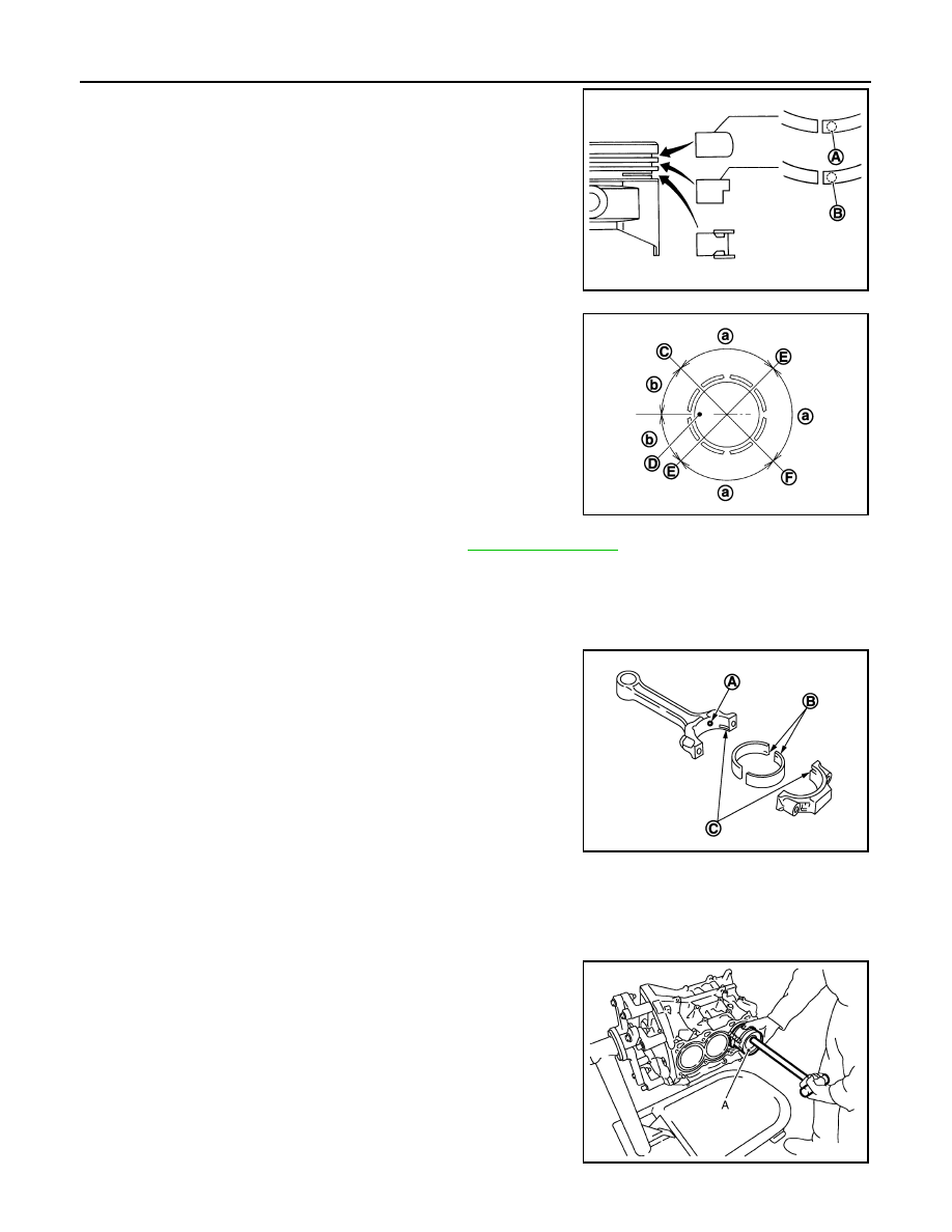
• If there is stamped mark on ring, mount it with marked side up.

NOTE:
If there is no stamp on ring, no specific orientation is required
for installation.

• Position each ring with the gap as shown in the figure referring

to the piston front mark (D).

• Check the piston rings side clearance. Refer to 

EM-119, "Inspection"

.

11. Install connecting rod bearings to connecting rod and connecting rod bearing cap.

CAUTION:

Be careful not to drop connecting rod bearing, and to scratch the surface.
• Before installing connecting rod bearings, apply engine oil to the bearing surface (inside). Do not apply

engine oil to the back surface, but thoroughly clean it. 

• When installing, align connecting rod bearing stopper protru-

sion (B) with cutout (C) of connecting rod and connecting rod
bearing cap to install. 

• Ensure the oil hole (A) on connecting rod and that on the cor-

responding bearing are aligned. 

12. Install piston and connecting rod assembly to crankshaft. 

• Position crankshaft pin corresponding to connecting rod to be installed onto the bottom dead center. 
• Apply engine oil sufficiently to the cylinder bore, piston and crankshaft pin journal.
• Match the cylinder position with the cylinder number on connecting rod to install. 
• Be sure that front mark on piston crown is facing front of engine.
• Using a piston ring compressor [SST: EM03470000 (J8037)]

(A) or suitable tool, install piston with the front mark on the pis-
ton crown facing the front of the engine.

CAUTION:

Be careful not to damage the cylinder wall and crankshaft
pin, resulting from an interference of the connecting rod big
end.

Stamped mark:

VQ25DE

VQ35DE

Top ring (A)

: R

: —

Second ring (B)

: R 2

: 2 R

JPBIA0263ZZ

C

: Top ring gap

E

: Oil ring upper or lower rail gap (either of then)

F

: Second ring and oil ring spacer gap

a

: 90 degrees

b

: 45 degrees

JPBIA0205ZZ

JPBIA0206ZZ

JPBIA0207ZZ

CYLINDER BLOCK

EM-117

< DISASSEMBLY AND ASSEMBLY >

C

D

E

F

G

H

I

J

K

L

M

A

EM

N

P

O

13. Install connecting rod bearing cap.

• Match the stamped cylinder number marks on connecting rod

with those on connecting rod bearing cap to install.

• Be sure that front mark (H) on connecting rod bearing cap is facing front of the engine.

14. Tighten connecting rod bolt as follows:
a.

Inspect the outer diameter of connecting rod bolt. Refer to 

EM-119, "Inspection"

.

b.

Apply engine oil to the threads and seats of connecting rod bolts. 

c.

Tighten connecting rod bolts.

d.

Then tighten all connecting rod bolts 90 degrees clockwise (angle tightening).

CAUTION:

Always use the angle wrench [SST: KV10112100 (BT8653-
A)]. Avoid tightening based on visual check alone.
• After tightening connecting rod bolts, check that crankshaft

rotates smoothly.

• Check the connecting rod side clearance. Refer to 

EM-119,

"Inspection"

.

15. Install baffle plate to main bearing beam.

16. Install new rear oil seal retainer to cylinder block. Refer to 

EM-94, "REAR OIL SEAL : Removal and Instal-

lation"

.

17. Install pilot converter.

• With drift [outer diameter: approximately 33 mm (1.30 in)],

press-fit as far as it will go.

A

:  Sample  codes

B

: Bearing stopper groove

C

: Small-end diameter grade

D

: Standard stamp

E

: Weight grade

F

: Cylinder No.

G

: Management code

I

: Management code

JPBIA0208ZZ

: 19.6 N·m (2.0 kg-m, 14 ft-lb)

SEM953E

PBIC0899E

EM-118

< DISASSEMBLY AND ASSEMBLY >

CYLINDER BLOCK

• Press-fit pilot converter with its chamfer facing crankshaft as

shown in the figure.

18. Install knock sensors.

• VQ25DE
- Install knock sensor so that connector faces the front of the

engine.

- After installing knock sensor, connect harness connector, and

lay it out to rear of engine.

CAUTION:

• Never tighten mounting bolts while holding connector.   
• If any impact by dropping is applied to knock sensor,

replace it with new one.

NOTE:
• Check that there is no foreign material on the cylinder block

mating surface and the back surface of knock sensor. 

• Check that knock sensor does not interfere with other parts.

• VQ35DE
- Install knock sensor so that connector faces the rear of the

engine.

- After installing knock sensor, connect harness connector, and

lay it out to rear of engine.

CAUTION:

• Never tighten mounting bolts while holding connector.   
• If any impact by dropping is applied to knock sensor,

replace it with new one.

NOTE:
• Check that there is no foreign material on the cylinder block

mating surface and the back surface of knock sensor. 

• Check that knock sensor does not interfere with other parts.

19. Note the following, assemble in the reverse order of disassem-

bly after this step.

Drive plate

• When installing drive plate to crankshaft, be sure to correctly

align crankshaft side dowel pin and drive plate side dowel pin
hole.

- If these are not aligned correctly, engine runs roughly and “MI” turns on.

: Crankshaft side

JPBIA0210ZZ

PBIC0810E

A

:  Bank  1

B

:  Bank  2

: Engine front

JPBIA0211ZZ

CYLINDER BLOCK

EM-119

< DISASSEMBLY AND ASSEMBLY >

C

D

E

F

G

H

I

J

K

L

M

A

EM

N

P

O

• Install drive plate (2) and reinforcement plate (3) as shown in

the figure.

• Holding ring gear with the pulley holder (commercial service

tool).

• Tighten mounting bolts crosswise over several times.

Inspection

INFOID:0000000003802295

CRANKSHAFT END PLAY

• Measure the clearance between thrust bearings and crankshaft

arm when crankshaft is moved fully forward or backward with a dial
indicator.

• If the measured value exceeds the limit, replace thrust bearings,

and measure again. If it still exceeds the limit, replace crankshaft
also.

CONNECTING ROD SIDE CLEARANCE

• Measure the side clearance between connecting rod and crank-

shaft arm with a feeler gauge (A).

• If the measured value exceeds the limit, replace connecting rod,

and measure again. If it still exceeds the limit, replace crankshaft
also.

PISTON TO PISTON PIN OIL CLEARANCE

Piston Pin Hole Diameter

Measure the inner diameter of piston pin hole with an inside
micrometer (A).

Piston Pin Outer Diameter

1

: Ring gear

4

: Pilot converter

5

: Crankshaft

A

: Rounded

: Engine front

JPBIA0212ZZ

Standard and limit

: Refer to 

EM-143, "Cylinder Block"

.

EMQ0196D

Standard and limit

: Refer to 

EM-143, "Cylinder Block"

.

JPBIA0536ZZ

Standard

: Refer to 

EM-143, "Cylinder Block"

.

JPBIA0217ZZ


Content   ..  496  497  498  499   ..