Nissan Teana J32. Manual - part 490
EM-84
< DISASSEMBLY AND ASSEMBLY >
CAMSHAFT
CAMSHAFT
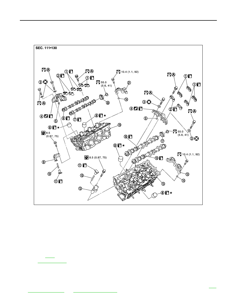
Exploded View
INFOID:0000000003802283
Removal and Installation
INFOID:0000000003802284
REMOVAL
1.
Remove front timing chain case, camshaft sprocket, timing chain and rear timing chain case. Refer to
1.
Camshaft bracket (No. 3, 4)
2.
Camshaft bracket (No. 2)
3.
Seal washer
4.
Camshaft bracket (No. 1)
5.
Dowel pin
6.
Camshaft (EXH) (bank 1)
7.
Camshaft (INT) (bank 1)
8.
Valve lifter
9.
Timing chain tensioner (secondary)
(bank 1)
10. Spring
11.
Plunger
12.
Timing chain tensioner (secondary)
(bank 2)
13. Cylinder head (bank 2)
14.
Dowel pin
15. Camshaft sensor bracket
16. Camshaft (EXH)
17.
Camshaft signal plate (INT)
18. Camshaft (INT)
19. Cylinder head (bank 1)
20.
Camshaft signal plate (INT)
21. Camshaft sensor bracket
A.
Refer to
Refer to
for symbols in the figure.
JPBIA1719GB