Nissan Teana J32. Manual - part 445


  Index      Nissan     Nissan Teana J32 (2008 year) - Service and Repair Manual


Search            


Content   ..  443  444  445  446   ..


Nissan Teana J32. Manual - part 445


EC-318

< COMPONENT DIAGNOSIS >

[VQ25DE, VQ35DE]

P2A00, P2A03 A/F SENSOR 1

P2A00, P2A03 A/F SENSOR 1

Description

INFOID:0000000003856817

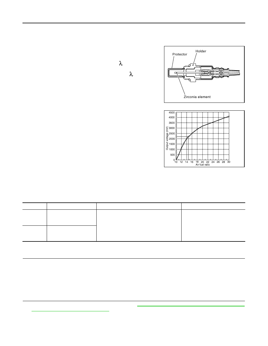
The air fuel ratio (A/F) sensor 1 is a planar one-cell limit current sen-
sor. The sensor element of the A/F sensor 1 is composed an elec-
trode layer, which transports ions. It has a heater in the element.
The sensor is capable of precise measurement   = 1, but also in the
lean and rich range. Together with its control electronics, the sensor
outputs a clear, continuous signal throughout a wide   range.
The exhaust gas components diffuse through the diffusion layer at
the sensor cell. An electrode layer is applied voltage, and this current
relative oxygen density in lean. Also this current relative hydrocar-
bon density in rich.

Therefore, the A/F sensor 1 is able to indicate air fuel ratio by this
electrode layer of current. In addition, a heater is integrated in the
sensor to ensure the required operating temperature of about 800

°

C

(1,472

°

F).

DTC Logic

INFOID:0000000003856818

DTC DETECTION LOGIC

To judge the malfunction, the A/F signal computed by ECM from the A/F sensor 1 signal is monitored so it will
not shift to LEAN side or RICH side.

DTC CONFIRMATION PROCEDURE

1.

PRECONDITIONING

If DTC Confirmation Procedure has been previously conducted, always turn ignition switch OFF and wait at
least 10 seconds before conducting the next test.
TESTING CONDITION:
Before performing the following procedure, confirm that battery voltage is more than 11 V at idle.

>> GO TO 2.

2.

PERFORM DTC CONFIRMATION PROCEDURE

1.

Clear the mixture ratio self-learning value. Refer to 

EC-18, "MIXTURE RATIO SELF-LEARNING VALUE

CLEAR : Special Repair Requirement"

.

2.

Turn ignition switch OFF and wait at least 10 seconds.

3.

Turn ignition switch ON.

4.

Turn ignition switch OFF and wait at least 10 seconds.

5.

Start engine and keep the engine speed between 3,500 and 4,000 rpm for 1 minute under no load.

JMBIA0112GB

PBIB3354E

DTC No.

Trouble diagnosis name

DTC detecting condition

Possible Cause

P2A00

Air fuel ratio (A/F) sensor 1 
(bank 1) circuit range/per-
formance

• The output voltage computed by ECM from the 

A/F sensor 1 signal shifts to the lean side for a 
specified period.

• The A/F signal computed by ECM from the A/F 

sensor 1 signal shifts to the rich side for a spec-
ified period.

• A/F sensor 1
• A/F sensor 1 heater
• Fuel pressure
• Fuel injector
• Intake air leaks

P2A03

Air fuel ratio (A/F) sensor 1 
(bank 2) circuit range/per-
formance

P2A00, P2A03 A/F SENSOR 1

EC-319

< COMPONENT DIAGNOSIS >

[VQ25DE, VQ35DE]

C

D

E

F

G

H

I

J

K

L

M

A

EC

N

P

O

6.

Let engine idle for 1 minute.

7.

Keep engine speed between 2,500 and 3,000 rpm for 20 minutes.

8.

Check 1st trip DTC.

Is 1st trip DTC detected?

YES

>> Go to 

EC-319, "Diagnosis Procedure"

.

NO

>> INSPECTION END

Diagnosis Procedure

INFOID:0000000003856819

1.

CHECK GROUND CONNECTION

1.

Turn ignition switch OFF.

2.

Check ground connection E38. Refer to Ground Inspection in 

GI-37, "Circuit Inspection"

.

Is the inspection result normal?

YES

>> GO TO 2.

NO

>> Repair or replace ground connection.

2.

RETIGHTEN A/F SENSOR 1

Loosen and retighten the A/F sensor 1. Refer to 

EM-34, "Removal and Installation"

.

>> GO TO 3.

3.

CHECK FOR INTAKE AIR LEAK

1.

Start engine and run it at idle.

2.

Listen for an intake air leak after the mass air flow sensor.

Is intake air leak detected?

YES

>> GO TO 4.

NO

>> Repair or replace malfunctioning part.

4.

CLEAR THE MIXTURE RATIO SELF-LEARNING VALUE

1.

Clear the mixture ratio self-learning value. Refer to 

EC-18, "MIXTURE RATIO SELF-LEARNING VALUE

CLEAR : Special Repair Requirement"

.

2.

Run engine for at least 10 minutes at idle speed.

Is the 1st trip DTC P0171, P0172, P0174 or P0175 detected? Is it difficult to start engine?

YES

>> Perform trouble diagnosis for DTC P0171, P0174 or P0172, P0175. Refer to 

EC-198, "DTC Logic"

or 

EC-202, "DTC Logic"

.

NO

>> GO TO 5.

5.

CHECK HARNESS CONNECTOR

1.

Turn ignition switch OFF.

2.

Disconnect A/F sensor 1 harness connector.

3.

Check harness connector for water.

Is the inspection result normal?

YES

>> GO TO 6.

NO

>> Repair or replace harness connector.

6.

CHECK AIR FUEL RATIO (A/F) SENSOR 1 POWER SUPPLY CIRCUIT

1.

Disconnect A/F sensor 1 harness connector.

2.

Turn ignition switch ON.

3.

Check the voltage between A/F sensor 1 harness connector and ground.

Water should not exit.

DTC

A/F sensor

Ground

Voltage (V)

Bank

Connector

Terminal

P2A00

1

F27

4

Ground

Battery voltage

P2A03

2

F64

4

EC-320

< COMPONENT DIAGNOSIS >

[VQ25DE, VQ35DE]

P2A00, P2A03 A/F SENSOR 1

Is the inspection result normal?

YES

>> GO TO 8.

NO

>> GO TO 7.

7.

DETECT MALFUNCTIONING PART

Check the following.
• IPDM E/R harness connector F12
• 15A fuse (No. 46)
• Harness for open or short between A/F sensor 1 and fuse

>> Repair or replace harness or connectors.

8.

CHECK A/F SENSOR 1 INPUT SIGNAL CIRCUIT FOR OPEN AND SHORT

1.

Turn ignition switch OFF.

2.

Disconnect ECM harness connector.

3.

Check the continuity between A/F sensor 1 harness connector and ECM harness connector.

4.

Check the continuity between A/F sensor 1 harness connector or ECM harness connector and ground.

5.

Also check harness for short to power.

Is the inspection result normal?

YES

>> GO TO 9.

NO

>> Repair open circuit, short to ground or short to power in harness or connectors.

9.

CHECK INTERMITTENT INCIDENT

Perform 

GI-35, "Intermittent Incident"

.

Is the inspection result normal?

YES

>> GO TO 10.

NO

>> Repair or replace malfunctioning part.

10.

REPLACE AIR FUEL RATIO (A/F) SENSOR 1

Replace malfunctioning air fuel ratio (A/F) sensor 1.

CAUTION:

• Discard any A/F sensor which has been dropped from a height of more than 0.5 m (19.7 in) onto a

hard surface such as a concrete floor; use a new one.

• Before installing new A/F sensor, clean exhaust system threads using Oxygen Sensor Thread

Cleaner and approved anti-seize lubricant.

>> INSPECTION END

DTC

A/F sensor 1

ECM

Continuity

Bank

Connector

Terminal

Connector

Terminal

P2A00

1

F27

1

F8

45

Existed

2

49

P2A03

2

F64

1

53

2

57

DTC

A/F sensor 1

ECM

Ground

Continuity

Bank

Connector

Terminal

Connector

Terminal

P2A00

1

F27

1

F8

45

Ground

Not existed

2

49

P2A03

2

F64

1

53

2

57

ASCD BRAKE SWITCH

EC-321

< COMPONENT DIAGNOSIS >

[VQ25DE, VQ35DE]

C

D

E

F

G

H

I

J

K

L

M

A

EC

N

P

O

ASCD BRAKE SWITCH

Description

INFOID:0000000003858142

When the brake pedal is depressed, ASCD brake switch is turned OFF and stop lamp switch is turned ON.
ECM detects the state of the brake pedal by two kinds of input (ON/OFF signal).
Refer to 

EC-51, "System Diagram"

 for the ASCD function.

Component Function Check

INFOID:0000000003856821

1.

CHECK ASCD BRAKE SWITCH FUNCTION

 With CONSULT-III

1.

Turn ignition switch ON.

2.

Select “BRAKE SW1” in “DATA MONITOR” mode with CONSULT-III.

3.

Check “BRAKE SW1” indication under the following conditions.

 Without CONSULT-III

1.

Turn ignition switch ON.

2.

Check the voltage between ECM harness connector and ground.

Is the inspection result normal?

YES

>> INSPECTION END

NO

>> Go to 

EC-321, "Diagnosis Procedure"

.

Diagnosis Procedure

INFOID:0000000003856822

1.

CHECK ASCD BRAKE SWITCH POWER SUPPLY CIRCUIT

1.

Turn ignition switch OFF.

2.

Disconnect ASCD brake switch harness connector.

3.

Turn ignition switch ON.

4.

Check the voltage between ASCD brake switch harness connector and ground.

Is the inspection result normal?

YES

>> GO TO 3.

NO

>> GO TO 2.

2.

DETECT MALFUNCTIONING PART

Check the following.
• Fuse block (J/B) connector E103
• 10A fuse (No.3)
• Harness for open or short between ASCD brake switch and fuse

>> Repair open circuit, short to ground or short to power in harness or connectors.

Monitor item

Condition

Indication

BRAKE SW1

Brake pedal

Slightly depressed

OFF

Fully released

ON

ECM

Ground

Condition

Voltage

Connector

Terminal

E16

110

(ASCD brake 

switch signal)

Ground

Brake pedal

Slightly depressed

Approx. 0 V

Fully released

Battery voltage

ASCD brake switch

Ground

Voltage

Connector

Terminal

E49

1

Ground

Battery voltage


Content   ..  443  444  445  446   ..