Nissan Teana J32. Manual - part 421


  Index      Nissan     Nissan Teana J32 (2008 year) - Service and Repair Manual


Search            


Content   ..  419  420  421  422   ..


Nissan Teana J32. Manual - part 421


EC-222

< COMPONENT DIAGNOSIS >

[VQ25DE, VQ35DE]

P0340, P0345 CMP SENSOR (PHASE)

P0340, P0345 CMP SENSOR (PHASE)

Description

INFOID:0000000003856627

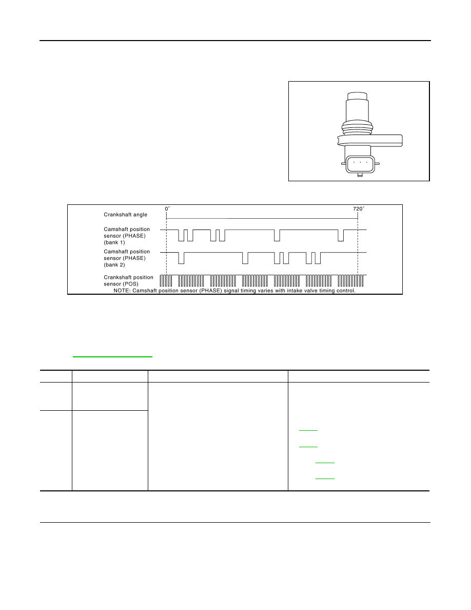
The camshaft position sensor (PHASE) senses the retraction of
camshaft (INT) to identify a particular cylinder. The camshaft position
sensor (PHASE) senses the piston position.
When the crankshaft position sensor (POS) system becomes inoper-
ative, the camshaft position sensor (PHASE) provides various con-
trols of engine parts instead, utilizing timing of cylinder identification
signals.
The sensor consists of a permanent magnet and Hall IC.
When engine is running, the high and low parts of the teeth cause
the gap with the sensor to change.
The changing gap causes the magnetic field near the sensor to
change.
Due to the changing magnetic field, the voltage from the sensor changes. 
ECM receives the signals as shown in the figure.

DTC Logic

INFOID:0000000003856628

DTC DETECTION LOGIC

NOTE:
If DTC P0340 or P0345 is displayed with DTC P0643, first perform the trouble diagnosis for DTC P0643.
Refer to 

EC-243, "DTC Logic"

.

DTC CONFIRMATION PROCEDURE

1.

PRECONDITIONING

If DTC Confirmation Procedure has been previously conducted, always turn ignition switch OFF and wait at
least 10 seconds before conducting the next test.
TESTING CONDITION:
Before performing the following procedure, confirm that battery voltage is more than 10.5 V with igni-
tion switch ON.

JMBIA0064ZZ

JMBIA0001GB

DTC No.

Trouble diagnosis name

DTC detecting condition

Possible cause

P0340

Camshaft position sen-
sor (PHASE) (bank 1) 
circuit

• The cylinder No. signal is not sent to ECM for 

the first few seconds during engine cranking.

• The cylinder No. signal is not sent to ECM 

during engine running.

• The cylinder No. signal is not in the normal 

pattern during engine running.

• Harness or connectors

(The sensor circuit is open or shorted)

• Camshaft position sensor (PHASE)
• Camshaft (INT)
• Starter motor [VQ25DE engine (Refer to 

STR-5

)]

• Starter motor [VQ35DE engine (Refer to 

STR-6

)]

• Starting system circuit [VQ25DE engine (Re-

fer to 

STR-5

.)]

• Starting system circuit [VQ35DE engine (Re-

fer to 

STR-6

.)]

• Dead (Weak) battery

P0345

Camshaft position sen-
sor (PHASE) (bank 2) 
circuit

P0340, P0345 CMP SENSOR (PHASE)

EC-223

< COMPONENT DIAGNOSIS >

[VQ25DE, VQ35DE]

C

D

E

F

G

H

I

J

K

L

M

A

EC

N

P

O

>> GO TO 2.

2.

PERFORM DTC CONFIRMATION PROCEDURE-I

1.

Start engine and let it idle for at least 5 seconds.
If engine does not start, crank engine for at least 2 seconds.

2.

Check 1st trip DTC.

Is 1st trip DTC detected?

YES

>> Go to 

EC-223, "Diagnosis Procedure"

.

NO

>> GO TO 3.

3.

PERFORM DTC CONFIRMATION PROCEDURE-I

1.

Maintaining engine speed at more than 800 rpm for at least 5 seconds.

2.

Check 1st trip DTC.

Is 1st trip DTC detected?

YES

>> Go to 

EC-223, "Diagnosis Procedure"

.

NO

>> INSPECTION END

Diagnosis Procedure

INFOID:0000000003856629

1.

CHECK STARTING SYSTEM

Turn ignition switch to START position.
Does the engine turn over? Does the starter motor operate?

YES

>> GO TO 2.

NO

>> Check starting system. (Refer to 

STR-2, "Work Flow"

.)

2.

CHECK GROUND CONNECTION

1.

Turn ignition switch OFF.

2.

Check ground connection E38. Refer to Ground Inspection in 

GI-37, "Circuit Inspection"

.

Is the inspection result normal?

YES

>> GO TO 3.

NO

>> Repair or replace ground connection.

3.

CHECK CAMSHAFT POSITION (CMP) SENSOR (PHASE) POWER SUPPLY CIRCUIT

1.

Disconnect camshaft position (CMP) sensor (PHASE) harness connector.

2.

Turn ignition switch ON.

3.

Check the voltage between CMP sensor (PHASE) harness connector and ground

Is the inspection result normal?

YES

>> GO TO 4.

NO

>> Repair open circuit, short to ground or short to power in harness or connectors.

4.

CHECK CMP SENSOR (PHASE) GROUND CIRCUIT FOR OPEN AND SHORT

1.

Turn ignition switch OFF.

2.

Disconnect ECM harness connector.

3.

Check the continuity between CMP sensor (PHASE) harness connector and ECM harness connector.

4.

Also check harness for short to ground and short to power.

DTC

CMP sensor (PHASE)

Ground

Voltage (V)

Bank

Connector

Terminal

P0340

1

F26

1

Ground

Approx. 5

P0345

2

F69

1

DTC

CMP sensor (PHASE)

ECM

Continuity

Bank

Connector

Terminal

Connector

Terminal

P0340

1

F26

2

F8

64

Existed

P0345

2

F69

2

68

EC-224

< COMPONENT DIAGNOSIS >

[VQ25DE, VQ35DE]

P0340, P0345 CMP SENSOR (PHASE)

Is the inspection result normal?

YES

>> GO TO 5.

NO

>> Repair open circuit, short to ground or short to power in harness or connectors.

5.

CHECK CMP SENSOR (PHASE) INPUT SIGNAL CIRCUIT FOR OPEN AND SHORT

1.

Check the continuity between CMP sensor (PHASE) harness connector and ECM harness connector.

2.

Also check harness for short to ground and short to power.

Is the inspection result normal?

YES

>> GO TO 6.

NO

>> Repair open circuit, short to ground or short to power in harness or connectors.

6.

CHECK CAMSHAFT POSITION SENSOR (PHASE)

Refer to 

EC-224, "Component Inspection"

.

Is the inspection result normal?

YES

>> GO TO 7.

NO

>> Replace malfunctioning camshaft position sensor (PHASE).

7.

CHECK CAMSHAFT (INT)

Check the following.
• Accumulation of debris to the signal plate of camshaft rear end
• Chipping signal plate of camshaft rear end

Is the inspection result normal?

YES

>> GO TO 8.

NO

>> Remove debris and clean the signal plate of camshaft

rear end or replace camshaft.

8.

CHECK INTERMITTENT INCIDENT

Refer to 

GI-35, "Intermittent Incident"

.

>> INSPECTION END

Component Inspection

INFOID:0000000003856630

1.

CHECK CAMSHAFT POSITION SENSOR (PHASE)-I

1.

Turn ignition switch OFF.

2.

Loosen the fixing bolt of the sensor.

3.

Disconnect camshaft position sensor (PHASE) harness connector.

4.

Remove the sensor.

DTC

CMP sensor (PHASE)

ECM

Continuity

Bank

Connector

Terminal

Connector

Terminal

P0340

1

F26

3

F8

70

Existed

P0345

2

F69

3

69

JMBIA0058ZZ

P0340, P0345 CMP SENSOR (PHASE)

EC-225

< COMPONENT DIAGNOSIS >

[VQ25DE, VQ35DE]

C

D

E

F

G

H

I

J

K

L

M

A

EC

N

P

O

5.

Visually check the sensor for chipping.

Is the inspection result normal?

YES

>> GO TO 2.

NO

>> Replace malfunctioning camshaft position sensor

(PHASE).

2.

CHECK CAMSHAFT POSITION SENSOR (PHASE)-II

Check resistance camshaft position sensor (PHASE) terminals as per the following.

Is the inspection result normal?

YES

>> INSPECTION END

NO

>> Replace malfunctioning camshaft position sensor (PHASE).

JMBIA0065ZZ

Terminal No. (Polarity)

Resistance

1 (+) - 2 (-)

Except 0 or 

∞Ω

 [at 25

°

C (77

°

F)]

1 (+) - 3 (-)

2 (+) - 3 (-)


Content   ..  419  420  421  422   ..