Nissan Teana J32. Manual - part 151
AV
U12A0 GPS ANTENNA
AV-459
< COMPONENT DIAGNOSIS >
[BOSE AUDIO WITH NAVIGATION]
C
D
E
F
G
H
I
J
K
L
M
B
A
O
P
U12A0 GPS ANTENNA
Description
INFOID:0000000003765866
DTC Logic
INFOID:0000000003765867
DTC DETECTION LOGIC
Diagnosis Procedure
INFOID:0000000003765868
1.
GPS ANTENNA CHECK
Visually check GPS antenna and antenna feeder.
Is inspection result normal?
YES
>> GO TO 2.
NO
>> Repair malfunctioning parts.
2.
CHECK NAVI CONTROL UNIT VOLTAGE
1.
Turn ignition switch OFF.
2.
Disconnect GPS antenna connector.
3.
Turn ignition switch ON.
4.
Check voltage between NAVI control unit terminal and ground.
Is inspection result normal?
YES
>> Replace GPS antenna.
NO
>> Replace NAVI control unit.
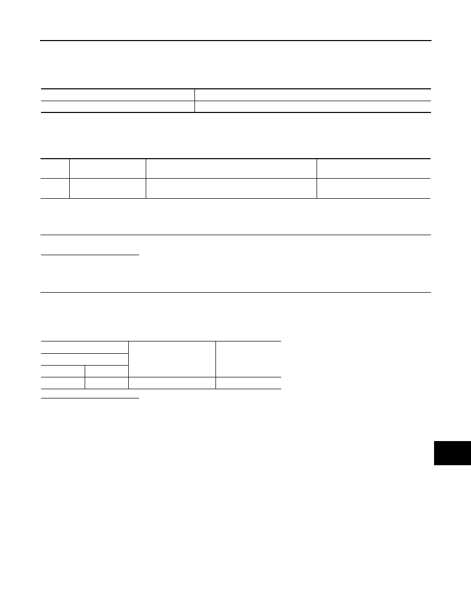
Part name
Description
GPS ANTENNA
GPS signal is received and transmitted to NAVI control unit.
DTC
Display contents of
CONSULT-III
DTC Detection Condition
Possible causes
U12A0
GPS ANTENNA CONN
[U12A0]
GPS antenna connection malfunction is detected.
GPS antenna.
(+)
(
−
)
Voltage
(Approx.)
NAVI control unit
Connector
Terminal
B474
49
Ground
5.0 V