Nissan Teana J32. Manual - part 1233


  Index      Nissan     Nissan Teana J32 (2008 year) - Service and Repair Manual


Search            


Content   ..  1231  1232  1233  1234   ..


Nissan Teana J32. Manual - part 1233


VTL-118

< ON-VEHICLE REPAIR >

[WITH 7 INCH DISPLAY]

DUCT AND GRILLE

FOOT DUCT : Removal and Installation

INFOID:0000000003894550

REMOVAL

Driver side

1.

Remove instrument driver lower panel. Refer to 

IP-11, "Exploded View"

.

2.

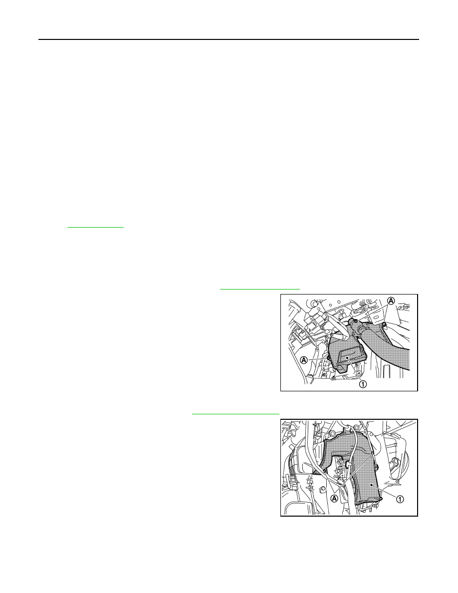
Remove mounting screws (A), and then remove foot duct (left)
(1).

Passenger side

1.

Remove blower unit assembly. Refer to 

VTL-87, "Exploded View"

.

2.

Remove mounting screws (A) and harness clip, and then
remove foot duct (right) (1).

INSTALLATION

Installation is basically the reverse order of removal.

1.

Ventilator seal

2.

Defroster seal

3.

Distributor upper case

4.

Center case

5.

Heater & cooling unit case cover

6.

Foot duct 1 (right)

7.

Foot duct 2 (right)

8.

Air mix door motor (passenger side)

9.

Evaporator pipe assembly

10. Expansion valve

11.

O-ring

12.

Evaporator

13. Filter cover

14.

Air conditioner filter

15.

Case packing

16. Heater & cooling unit case (right)

17.

Cooler pipe grommet

18.

Grommet

19. Heater pipe grommet

20.

Heater pipe support

21.

Drain hose

22. Heater & cooling unit case (left)

23.

Air mix door motor (driver side)

24.

Heater core 

25. Heater pipe cover

26.

Foot duct 2 (left)

27.

Foot duct 1 (left)

28. Aspirator hose

29.

Aspirator

30.

Mode door motor

31. Main link

32.

Rod link

33.

Ventilator door link

34. Mode door lever

35.

Ventilator door lever

36.

Max. cool door link

37. Defroster door link

38.

Foot door link

39.

Max. cool door lever

40. Foot door lever

41.

Defroster door lever

42.

Adapter case

43. Distributor lower case

44.

Ventilator door

45.

Intake sensor

46. Intake sensor bracket

47.

Foot door

48.

Max. cool door

49. Defroster door

50.

Air mix door (Slide door)

Refer to 

GI-4, "Components"

 for symbols in the figure.

JPIIA0944ZZ

JPIIA0945ZZ

IONIZER

VTL-119

< ON-VEHICLE REPAIR >

[WITH 7 INCH DISPLAY]

C

D

E

F

G

H

J

K

L

M

A

B

VTL

N

O

P

IONIZER

WITH INTELLIGENT AIR CONDITIONER SYSTEM

WITH INTELLIGENT AIR CONDITIONER SYSTEM : Exploded View

INFOID:0000000003894551

WITH INTELLIGENT AIR CONDITIONER SYSTEM : Removal and Installation

INFOID:0000000003894552

REMOVAL

1.

Remove ventilator duct. Refer to 

VTL-106, "VENTILATOR DUCT : Exploded View"

.

2.

Remove mounting clips (A), and then remove ionizer (1).

CAUTION:

Never touch the front surface (ceramic part) of ionizer. It is
the discharge electrode.

INSTALLATION

installation is basically the reverse order of removal.

CAUTION:

If there is dirt, use a clean cloth and clean the discharge electrode (ceramic) of ionizer.

1.

Ventilator duct

2.

Ionizer

3.

Ionizer bracket

JPIIA0946ZZ

JPIIA0947ZZ

WCS

WCS-1

DRIVER INFORMATION & MULTIMEDIA

C

D

E

F

G

H

I

J

K

L

M

B

SECTION 

WCS

A

O

P

CONTENTS

WARNING CHIME SYSTEM

BASIC INSPECTION  ....................................

3

DIAGNOSIS AND REPAIR WORKFLOW  ..........

3

Work Flow  .................................................................

3

FUNCTION DIAGNOSIS ...............................

5

WARNING CHIME SYSTEM  ...............................

5

WARNING CHIME SYSTEM  .......................................

5

WARNING CHIME SYSTEM : System Diagram .......

5

WARNING CHIME SYSTEM : System Description 

......

5

WARNING CHIME SYSTEM : Component Parts 
Location ...................................................................
..

6

WARNING CHIME SYSTEM : Component De-
scription ...................................................................
..

6

LIGHT REMINDER WARNING CHIME  .......................

6

LIGHT REMINDER WARNING CHIME : System 
Diagram ...................................................................
..

7

LIGHT REMINDER WARNING CHIME : System 
Description ..............................................................
..

7

LIGHT REMINDER WARNING CHIME : Compo-
nent Parts Location  .................................................
..

8

LIGHT REMINDER WARNING CHIME : Compo-
nent Description  ......................................................
..

8

PARKING BRAKE RELEASE WARNING CHIME ......

8

PARKING BRAKE RELEASE WARNING CHIME 
: System Diagram ....................................................
..

9

PARKING BRAKE RELEASE WARNING CHIME 
: System Description  ...............................................
..

9

PARKING BRAKE RELEASE WARNING CHIME 
: Component Parts Location ....................................

10

PARKING BRAKE RELEASE WARNING CHIME 
: Component Description .........................................

10

DIAGNOSIS SYSTEM (METER) ........................

11

Diagnosis Description  .............................................

11

CONSULT-III Function (METER/M&A)  ...................

12

DIAGNOSIS SYSTEM (BCM)  ...........................

16

COMMON ITEM  .........................................................

16

COMMON ITEM : CONSULT-III Function (BCM - 
COMMON ITEM)  .....................................................

16

BUZZER .....................................................................

17

BUZZER : CONSULT-III Function (BCM - BUZZ-
ER) ..........................................................................

17

COMPONENT DIAGNOSIS .........................

19

POWER SUPPLY AND GROUND CIRCUIT  ....

19

COMBINATION METER  ............................................

19

COMBINATION METER : Diagnosis Procedure  .....

19

BCM (BODY CONTROL MODULE)  ..........................

19

BCM (BODY CONTROL MODULE) : Diagnosis 
Procedure ................................................................

19

METER BUZZER CIRCUIT  ...............................

21

Description ...............................................................

21

Component Function Check  ....................................

21

Diagnosis Procedure ..............................................

21

WARNING CHIME SYSTEM .............................

22

Wiring Diagram - WARNING CHIME -  ....................

22

ECU DIAGNOSIS .........................................

26

COMBINATION METER  ...................................

26

Reference Value ......................................................

26

Wiring Diagram - METER - ......................................

32

Fail-Safe ..................................................................

39

DTC Index  ...............................................................

40

BCM (BODY CONTROL MODULE)  .................

41

Reference Value ......................................................

41

Wiring Diagram - BCM -  ..........................................

64

Fail-safe ...................................................................

70

DTC Inspection Priority Chart ...............................

72

DTC Index ...............................................................

73


Content   ..  1231  1232  1233  1234   ..