Nissan Teana J32. Manual - part 1218


  Index      Nissan     Nissan Teana J32 (2008 year) - Service and Repair Manual


Search            


Content   ..  1216  1217  1218  1219   ..


Nissan Teana J32. Manual - part 1218


VTL-58

< ON-VEHICLE REPAIR >

[WITHOUT 7 INCH DISPLAY]

DUCT AND GRILLE

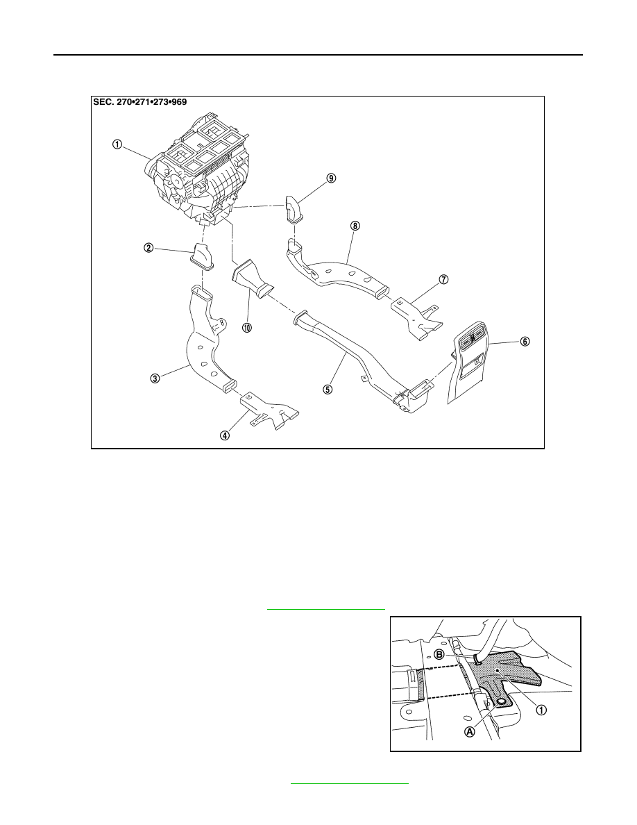
REAR FOOT DUCT 3 : Exploded View

INFOID:0000000003774713

REAR FOOT DUCT 3 : Removal and Installation

INFOID:0000000003774714

REMOVAL

Driver side

1.

Pull up driver side floor carpet. Refer to 

INT-47, "Exploded View"

2.

Remove mounting clip (A) and harness clip (B), and then
remove rear foot duct 3 (left) (1). 

Passenger side

1.

Pull up passenger side floor carpet. Refer to 

INT-47, "Exploded View"

1.

Heater & cooling unit assembly

2.

Rear foot duct 1 (left)

3.

Rear foot duct 2 (left)

4.

Rear foot duct 3 (left)

5.

Rear ventilator duct 2

6.

Console rear cover (Rear 
ventilator grille)

7.

Rear foot duct 3 (right)

8.

Rear foot duct 2 (right)

9.

Rear foot duct 1 (right)

10.

Rear ventilator duct 1

JPIIA0935ZZ

JPIIA0942ZZ

DUCT AND GRILLE

VTL-59

< ON-VEHICLE REPAIR >

[WITHOUT 7 INCH DISPLAY]

C

D

E

F

G

H

J

K

L

M

A

B

VTL

N

O

P

2.

Remove mounting clip (A) and harness clip (B), and then
remove rear foot duct 3 (right) (1). 

INSTALLATION

Installation is basically the reverse order of removal.

FOOT DUCT

FOOT DUCT : Exploded View

INFOID:0000000003821492

JPIIA0943ZZ

JPIIA0906GB

VTL-60

< ON-VEHICLE REPAIR >

[WITHOUT 7 INCH DISPLAY]

DUCT AND GRILLE

FOOT DUCT : Removal and Installation

INFOID:0000000003774716

REMOVAL

Driver side

1.

Remove instrument driver lower panel. Refer to 

IP-11, "Exploded View"

.

2.

Remove mounting screws (A), and then remove foot duct (left)
(1).

Passenger side

1.

Remove blower unit assembly. Refer to 

VTL-29, "Exploded View"

.

2.

Remove mounting screws (A) and harness clip, and then
remove foot duct (right) (1).

INSTALLATION

Installation is basically the reverse order of removal.

1.

Ventilator seal

2.

Defroster seal

3.

Distributor upper case

4.

Center case

5.

Heater & cooling unit case cover

6.

Foot duct 1 (right)

7.

Foot duct 2 (right)

8.

Air mix door motor (passenger side)

9.

Evaporator pipe assembly

10. Expansion valve

11.

O-ring

12.

Evaporator

13. Filter cover

14.

Air conditioner filter

15.

Case packing

16. Heater & cooling unit case (right)

17.

Cooler pipe grommet

18.

Grommet

19. Heater pipe grommet

20.

Heater pipe support

21.

Drain hose

22. Heater & cooling unit case (left)

23.

Air mix door motor (driver side)

24.

Heater core 

25. Heater pipe cover

26.

Foot duct 2 (left)

27.

Foot duct 1 (left)

28. Aspirator hose

29.

Aspirator

30.

Mode door motor

31. Main link

32.

Rod link

33.

Ventilator door link

34. Mode door lever

35.

Ventilator door lever

36.

Max. cool door link

37. Defroster door link

38.

Foot door link

39.

Max. cool door lever

40. Foot door lever

41.

Defroster door lever

42.

Adapter case

43. Distributor lower case

44.

Ventilator door

45.

Intake sensor

46. Intake sensor bracket

47.

Foot door

48.

Max. cool door

49. Defroster door

50.

Air mix door (Slide door)

Refer to 

GI-4, "Components"

 for symbols in the figure.

JPIIA0944ZZ

JPIIA0945ZZ

SWITCHES AND THEIR CONTROL FUNCTION

VTL-61

< FUNCTION DIAGNOSIS >

[WITH 7 INCH DISPLAY]

C

D

E

F

G

H

J

K

L

M

A

B

VTL

N

O

P

FUNCTION DIAGNOSIS

SWITCHES AND THEIR CONTROL FUNCTION

WITHOUT INTELLIGENT AIR CONDITIONER SYSTEM

WITHOUT INTELLIGENT AIR CONDITIONER SYSTEM : System Description

INFOID:0000000003894439

JPIIA0885GB

JSIIA1189GB


Content   ..  1216  1217  1218  1219   ..