Nissan Teana J32. Manual - part 1129


  Index      Nissan     Nissan Teana J32 (2008 year) - Service and Repair Manual


Search            


Content   ..  1127  1128  1129  1130   ..


Nissan Teana J32. Manual - part 1129


TM-40

< FUNCTION DIAGNOSIS >

[CVT: RE0F09B]

DIAGNOSIS SYSTEM (TCM)

Diagnostic Tool Function

INFOID:0000000003848945

OBD SELF-DIAGNOSTIC PROCEDURE

Refer to 

EC-122, "Diagnosis Tool Function"

.

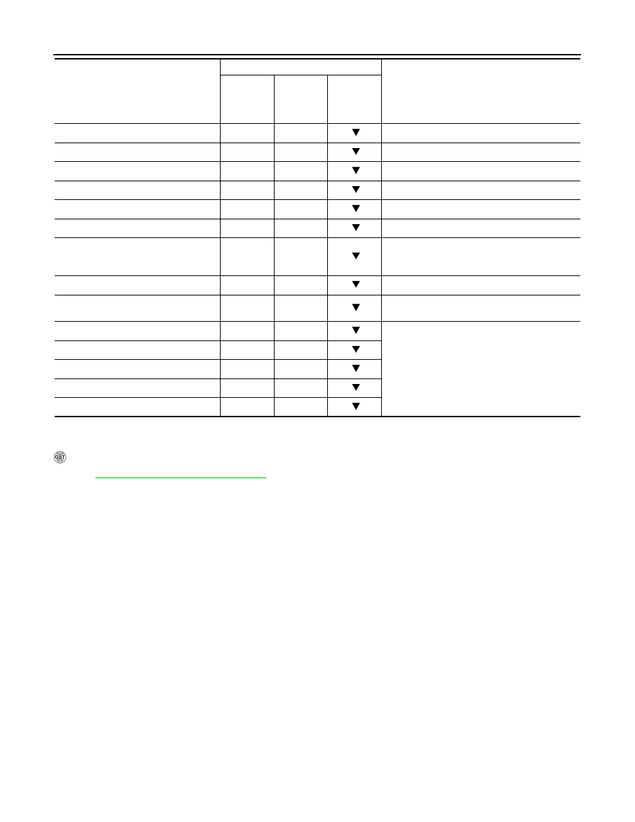
LUSEL SOL MON (On/Off)

STRTR RLY MON (On/Off)

Starter relay monitor

VDC ON (On/Off)

X

TCS ON (On/Off)

X

ABS ON (On/Off)

X

ACC ON (On/Off)

X

Not mounted but displayed.

RANGE

X

Indicates position is recognized by TCM. Indi-
cates a specific value required for control when 
fail-safe function is activated.

M GEAR POS

X

Not mounted but displayed.

Voltage (V) 

Displays the value measured by the voltage 
probe.

Frequency (Hz)

The value measured by the pulse probe is dis-
played.

DUTY-HI (high) (%)

DUTY-LOW (low) (%)

PLS WIDTH-HI (ms) 

PLS WIDTH-LOW (ms) 

Monitored item (Unit)

Monitor item selection

Remarks

 ECU IN-

PUT SIG-

NALS

MAIN SIG-

NALS

SELEC-

TION 

FROM 
MENU

U1000 CAN COMM CIRCUIT

TM-41

< COMPONENT DIAGNOSIS >

[CVT: RE0F09B]

C

E

F

G

H

I

J

K

L

M

A

B

TM

N

O

P

COMPONENT DIAGNOSIS

U1000 CAN COMM CIRCUIT

Description

INFOID:0000000003848946

CAN (Controller Area Network) is a serial communication line for real time application. It is an on-vehicle mul-
tiplex communication line with high data communication speed and excellent malfunction detection ability.
Many electronic control units are equipped onto a vehicle, and each control unit shares information and links
with other control units during operation (not independent). In CAN communication, control units are con-
nected with 2 communication lines (CAN-H and CAN-L) allowing a high rate of information transmission with
less wiring. Each control unit transmits/receives data but selectively reads required data only.

DTC Logic

INFOID:0000000003848947

DTC DETECTION LOGIC

DTC CONFIRMATION PROCEDURE

NOTE:
Immediately after performing any “DTC CONFIRMATION PROCEDURE”, always turn ignition switch OFF.
Then wait at least 10 seconds before performing the next test.

1.

CHECK DTC DETECTION

With CONSULT-III

1.

Turn ignition switch ON.

2.

Start engine and wait for at least 6 seconds.

3.

Perform “Self-Diagnostic Results” mode for “TRANSMISSION”.

With GST

Follow the procedure “With CONSULT-III”.

Is “U1000 CAN COMM CIRCUIT” detected?

YES

>> Go to 

TM-41, "Diagnosis Procedure"

.

NO

>> Check intermittent incident. Refer to 

GI-35, "Intermittent Incident"

.

Diagnosis Procedure

INFOID:0000000003848948

1.

CHECK CAN COMMUNICATION CIRCUIT

With CONSULT-III

1.

Turn ignition switch ON and start engine.

2.

Perform “Self-Diagnostic Results” mode for “TRANSMISSION”.

Is “U1000 CAN COMM CIRCUIT” indicated?

YES

>> Go to LAN section. Refer to 

LAN-22, "CAN System Specification Chart"

.

NO

>> Check intermittent incident. Refer to 

GI-35, "Intermittent Incident"

.

DTC

Item

(CONSULT-III screen term)

Malfunction is detected when...

Possible cause

U1000

CAN COMM CIRCUIT

When TCM is not transmitting or receiving 
CAN communication signal for 2 seconds or 
more.

Harness or connectors
(CAN communication line is open or short-
ed.)

TM-42

< COMPONENT DIAGNOSIS >

[CVT: RE0F09B]

P0615 START SIGNAL

P0615 START SIGNAL

Description

INFOID:0000000003848949

• TCM controls starter relay in IPDM E/R.
• TCM switches starter relay ON at “P” or “N” position and allows to crank engine. 
• Then it prohibits cranking other than at “P” or “N” position.

DTC Logic

INFOID:0000000003848950

DTC DETECTION LOGIC

DTC CONFIRMATION PROCEDURE

CAUTION:

Always drive vehicle at a safe speed.
NOTE:
Immediately after performing any “DTC CONFIRMATION PROCEDURE”, always turn ignition switch OFF.
Then wait at least 10 seconds before performing the next test.

1.

CHECK DTC DETECTION

With CONSULT-III

1.

Turn ignition switch ON.

2.

Perform “Self-Diagnostic Results” mode for “TRANSMISSION”.

Is “P0615 STARTER RELAY/CIRC” detected?

YES

>> Go to 

TM-42, "Diagnosis Procedure"

.

NO

>> Check intermittent incident. Refer to 

GI-35, "Intermittent Incident"

.

Diagnosis Procedure

INFOID:0000000003848951

1.

CHECK STARTER RELAY SIGNAL

1.

Turn ignition switch ON.

2.

Disconnect IPDM E/R harness connector.

3.

Check voltage between IPDM E/R vehicle side harness connector terminal and ground.

Is the inspection result normal?

YES

>> Check starter relay and starter control relay. Refer to 

STR-10, "Wiring Diagram - STARTING SYS-

TEM -"

.

NO

>> GO TO 2.

2.

CHECK HARNESS BETWEEN TCM AND IPDM E/R (PART 1)

1.

Turn ignition switch OFF.

2.

Disconnect TCM connector.

3.

Check continuity between TCM vehicle side harness connector terminal and IPDM E/R vehicle side har-
ness connector terminal.

DTC

Item

(CONSULT-III screen term)

Malfunction is detected when...

Possible cause

P0615

STARTER RELAY/CIRC

If this signal is ON other than in “P” or “N” po-
sition, this is judged to be a malfunction.
(And if it is OFF in “P” or “N” position, this too 
is judged to be a malfunction.)

• Harness or connectors

(Starter relay and TCM circuit is open or 
shorted.)

• Starter relay circuit

IPDM E/R vehicle side harness connector

Ground

Condition

Voltage (Approx.)

Connector

Terminal

F12

72

Selector lever in “P” and “N” positions

Battery voltage

Selector lever in other positions

0 V

P0615 START SIGNAL

TM-43

< COMPONENT DIAGNOSIS >

[CVT: RE0F09B]

C

E

F

G

H

I

J

K

L

M

A

B

TM

N

O

P

Is the inspection result normal?

YES

>> GO TO 3.

NO

>> Repair or replace damaged parts.

3.

CHECK HARNESS BETWEEN TCM AND IPDM E/R (PART 2)

Check continuity between TCM vehicle side harness connector terminal and ground.

Is the inspection result normal?

YES

>> GO TO 4.

NO

>> Repair or replace damaged parts.

4.

DETECT MALFUNCTIONING ITEMS

Check TCM connector pin terminals for damage or loose connection with harness connector.

Is the inspection result normal?

YES

>> Replace TCM. Refer to 

TM-153, "Exploded View"

.

NO

>> Repair or replace damaged parts.

TCM vehicle side harness connector

IPDM E/R vehicle side harness connector

Continuity

Connector

Terminal

Connector

Terminal

F23

20

F12

72

Existed

TCM vehicle side harness connector

Ground

Continuity

Connector

Terminal

F23

20

Not existed


Content   ..  1127  1128  1129  1130   ..