Nissan Teana J32. Manual - part 89


  Index      Nissan     Nissan Teana J32 (2008 year) - Service and Repair Manual


Search            


Content   ..  87  88  89  90   ..


Nissan Teana J32. Manual - part 89


AV

DIAGNOSIS SYSTEM (AV CONTROL UNIT)

AV-211

< FUNCTION DIAGNOSIS >

[BOSE AUDIO WITHOUT NAVIGATION]

C

D

E

F

G

H

I

J

K

L

M

B

A

O

P

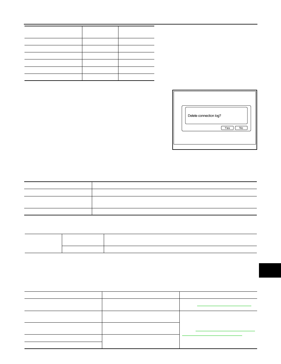
Delete Unit Connection Log

Deletes any unit connection records and error records from the AV
control unit memory. (Clear the records of the unit that has been
removed)

CONSULT-III Function (MULTI AV)

INFOID:0000000003765658

CONSULT-III FUNCTIONS

CONSULT-III performs the following functions via the communication with the AV control unit.

AV COMMUNICATION

When “AV communication” of “CAN Diag Support Monitor” is selected, the following function will be performed.

SELF-DIAGNOSIS RESULTS

• In CONSULT-III self-diagnosis, self-diagnosis results and error history are displayed collectively.
• The timing is displayed as “0” if any of the error codes [U1000], [U1010], [U1300] and [U1310] is detected.

The counter increases by 1 if the condition is normal at the next ignition switch ON cycle.

Self-diagnosis Results Display Item

C Rx(RrSeatSW–ITM)

OK / UNKWN

OK / 0 – 39

C Rx(Amp–ITM)

OK / UNKWN

OK / 0 – 39

C Rx(RearCamera–ITM)

OK / UNKWN

OK / 0 – 39

C Rx(DVD–ITM)

OK / UNKWN

OK / 0 – 39

C Rx(AmpAudio–ITM)

OK / UNKWN

OK / 0 – 39

C Rx(DVDAudio–ITM)

OK / UNKWN

OK / 0 – 39

Items

Status

(Current)

Counter

(Past)

JSNIA0154GB

Diagnosis mode

Description

Ecu Identification

The part number of AV control unit can be checked.

Self Diagnostic Result

Performs a diagnosis on the AV control unit and a connection diagnosis for the communication 
circuit of the Multi AV system, and displays the current and past malfunctions collectively.

Data Monitor

The diagnosis of vehicle signal that is input to the AV control unit can be performed.

AV communication

AV&NAVI C/U

Displays the communication status from AV control unit to each unit as well as the error 
counter.

AUDIO

Displays the AV control unit communication status and the error counter.

Error item

Detection logic

Possible malfunction factor/Action to take

CAN COMM CIRCUIT [U1000]

CAN communication malfunction is detect-
ed.

Refer to 

AV-216, "Diagnosis Procedure"

.

CONTROL UNIT (CAN) [U1010]

CAN initial diagnosis malfunction is detect-
ed.

Replace the AV control unit.
Refer to

AV-378, "Removal and Installation"


AV-378, "Removal and Installation"

.

CONTROL UNIT (AV) [U1310]

AV communication circuit initial diagnosis 
malfunction is detected.

Control Unit FLASH-ROM [U1200]

AV control unit malfunction is detected.

CAN CONT [U1216]

AV-212

< FUNCTION DIAGNOSIS >

[BOSE AUDIO WITHOUT NAVIGATION]

DIAGNOSIS SYSTEM (AV CONTROL UNIT)

AMP TEMP [U1231]

BOSE amp. is detected.

Replace the BOSE amp.
Refer to 

AV-386, "Removal and Installa-

tion"

.

FRONT DISP CONN [U1243]

When either one of the following items is 
detected:
• display unit power supply and ground cir-

cuits are malfunctioning.

• serial communication circuits between 

display unit and AV control unit are mal-
functioning.

• serial communication signal between 

display unit and AV control unit is mal-
functioning.

• Display unit power supply and ground 

circuits
Refer to 

AV-222, "Diagnosis Procedure"

.

• Serial communication circuits between 

display unit and AV control unit

CAMERA CONT. CONN [U1250]

Camera connection recognition signal cir-
cuit malfunction is detected.

Camera connection recognition signal cir-
cuit
Refer to 

AV-224, "Diagnosis Procedure"

.

CENTER SP OPEN [U1260]

Sound signal center speaker circuit is 
open.

Check sound signal center speaker circuit.

CENTER SP SHORT [U1261]

Sound signal center speaker circuit is 
shorted between center speaker signal (+) 
and center speaker signal (-).

Check sound signal center speaker circuit.

CENTER SP GND-SHORT [U1262]

Sound signal center speaker circuit to 
ground is shorted.

Check sound signal center speaker circuit.

CENTER SP VB-SHORT [U1263]

Sound signal center speaker circuit to bat-
tery is shorted.

Check sound signal center speaker circuit.

FR-DOOR SP OPEN [U1264]

Sound signal front speaker RH circuit is 
open.

Check sound signal front speaker RH cir-
cuit.

FR-DOOR SP SHORT [U1265]

Sound signal front speaker RH circuit is 
shorted between front speaker RH signal 
(+) and front speaker RH signal (-).

Check sound signal front speaker RH cir-
cuit.

FR-DOOR SP GND-SHORT [U1266]

Sound signal front speaker RH circuit to 
ground is shorted.

Check sound signal front speaker RH cir-
cuit.

FR-DOOR SP VB-SHORT [U1267]

Sound signal front speaker RH circuit to 
battery is shorted.

Check sound signal front speaker RH cir-
cuit.

RR-SP/FR-WOOFER OPEN [U1268]

Sound signal rear speaker RH circuit is 
open.

Check sound signal rear speaker RH cir-
cuit.

RR-SP/FR-WOOFER SHORT [U1269]

Sound signal rear speaker RH circuit is 
shorted between rear speaker LH signal (+) 
and rear speaker LH signal (-).

Check sound signal rear speaker RH cir-
cuit.

RR-SP/FR-WOOFER GND-SHORT 
[U126A]

Sound signal rear speaker RH circuit to 
ground is shorted.

Check sound signal rear speaker RH cir-
cuit.

RR-SP/FR-WOOFER VB-SHORT [U126B]

Sound signal rear speaker RH circuit to bat-
tery is shorted.

Check sound signal rear speaker RH cir-
cuit.

RR-SURROUND SP OPEN [U126C]

Sound signal woofer RH circuit is open.

Check sound signal woofer RH circuit.

RR-SURROUND SP SHORT [U126D]

Sound signal woofer RH circuit is shorted 
between woofer RH signal (+) and woofer 
RH signal (-).

Check sound signal woofer RH circuit.

RR-SURROUND SP GND-SHORT 
[U126E]

Sound signal woofer RH circuit to ground is 
shorted.

Check sound signal woofer RH circuit.

RR-SURROUND SP VB-SHORT [U126F]

Sound signal woofer RH circuit to battery is 
shorted.

Check sound signal woofer RH circuit.

RL-SURROUND SP OPEN [U1274]

Sound signal woofer LH circuit is open.

Check sound signal woofer LH circuit.

RL-SURROUND SP SHORT [U1275]

Sound signal woofer LH circuit is shorted 
between woofer LH signal (+) and woofer 
LH signal (-).

Check sound signal woofer LH circuit.

Error item

Detection logic

Possible malfunction factor/Action to take

AV

DIAGNOSIS SYSTEM (AV CONTROL UNIT)

AV-213

< FUNCTION DIAGNOSIS >

[BOSE AUDIO WITHOUT NAVIGATION]

C

D

E

F

G

H

I

J

K

L

M

B

A

O

P

RL-SURROUND SP GND-SHORT [U1276]

Sound signal woofer LH circuit to ground is 
shorted.

Check sound signal woofer LH circuit.

RL-SURROUND SP VB-SHORT [U1277]

Sound signal woofer LH circuit to battery is 
shorted.

Check sound signal woofer LH circuit.

RL-SP/FL-WOOFER OPEN [U1278]

Sound signal rear speaker LH circuit is 
open.

Check sound signal rear speaker LH circuit.

RL-SP/FL-WOOFER SHORT [U1279]

Sound signal rear speaker LH circuit is 
shorted between rear speaker LH signal (+) 
and rear speaker LH signal (-).

Check sound signal rear speaker LH circuit.

RL-SP/FL-WOOFER GND-SHORT 
[U127A]

Sound signal rear speaker LH circuit to 
ground is shorted.

Check sound signal rear speaker LH circuit.

RL-SP/FL-WOOFER VB-SHORT [U127B]

Sound signal rear speaker LH circuit to bat-
tery is shorted.

Check sound signal rear speaker LH circuit.

FL-DOOR SP OPEN [U127C]

Sound signal front speaker LH circuit is 
open.

Check sound signal front speaker LH cir-
cuit.

FL-DOOR SP SHORT [U127D]

Sound signal front speaker LH circuit is 
shorted between front speaker LH signal 
(+) and front speaker LH signal (-).

Check sound signal front speaker LH cir-
cuit.

FL-DOOR SP GND-SHORT [U127E]

Sound signal front speaker LH circuit to 
ground is shorted.

Check sound signal front speaker LH cir-
cuit.

FL-DOOR SP VB-SHORT [U127F]

Sound signal front speaker LH circuit to 
battery is shorted.

Check sound signal front speaker LH cir-
cuit.

FR-TWEETER OPEN [U1294]

Sound signal front squawker RH circuit is 
open.

Check sound signal front squawker RH cir-
cuit.

FR-TWEETER SHORT [U1295]

Sound signal front squawker RH circuit is 
shorted between front squawker RH signal 
(+) and front squawker RH signal (-).

Check sound signal front squawker RH cir-
cuit.

FR-TWEETER GND-SHORT [U1296]

Sound signal front squawker RH circuit to 
ground is shorted.

Check sound signal front squawker RH cir-
cuit.

FR-TWEETER VB-SHORT [U1297]

Sound signal front squawker RH circuit to 
battery is shorted.

Check sound signal front squawker RH cir-
cuit.

FL-TWEETER OPEN [U1298]

Sound signal front squawker LH circuit is 
open.

Check sound signal front squawker LH cir-
cuit.

FL-TWEETER SHORT [U1299]

Sound signal front squawker LH circuit is 
shorted between front squawker LH signal 
(+) and front squawker LH signal (-).

Check sound signal front squawker LH cir-
cuit.

FL-TWEETER GND-SHORT [U129A]

Sound signal front squawker LH circuit to 
ground is shorted.

Check sound signal front squawker LH cir-
cuit.

FL-TWEETER VB-SHORT [U129B]

Sound signal front squawker LH circuit to 
battery is shorted.

Check sound signal front squawker LH cir-
cuit.

• AV COMM CIRCUIT [U1300]
• SWITCH CONN [U1240]

When either one of the following items is 
detected:
• Multifunction switch power supply and 

ground circuits are malfunctioning.

• AV communication circuits between AV 

control unit and multifunction switch are 
malfunctioning.

• AV communication signal between AV 

control unit and multifunction switch is 
malfunctioning.

• Multifunction switch power supply and 

ground circuits
refer to 

AV-237, "MULTIFUNCTION 

SWITCH : Diagnosis Procedure"

.

• AV communication circuits between AV 

control unit and multifunction switch

Error item

Detection logic

Possible malfunction factor/Action to take

AV-214

< FUNCTION DIAGNOSIS >

[BOSE AUDIO WITHOUT NAVIGATION]

DIAGNOSIS SYSTEM (AV CONTROL UNIT)

DATA MONITOR

ALL SIGNALS

• Displays the status of the following vehicle signals inputted to the AV control unit.

• AV COMM CIRCUIT [U1300]
• AMP CONN [U124E]

When either one of the following items is 
detected:
• BOSE amp. power supply and ground 

circuits are malfunctioning.

• AV communication signal between AV 

control unit and BOSE amp. is malfunc-
tioning.

BOSE amp. power supply and ground cir-
cuits
Refer to 

AV-238, "BOSE AMP. : Diagnosis 

Procedure"

.

• AV COMM CIRCUIT [U1300]
• DVD DECK CONN [U1248]

When either one of the following items is 
detected:
• DVD player power supply and ground cir-

cuits are malfunctioning.

• AV communication circuits between 

BOSE amp. and DVD player are mal-
functioning.

• AV communication signal between AV 

control unit and DVD player is malfunc-
tioning.

• DVD player power supply and ground cir-

cuits
Refer to 

AV-239, "DVD PLAYER : Diag-

nosis Procedure"

• AV communication circuits between 

BOSE amp. and DVD player

• AV COMM CIRCUIT [U1300]
• AMP CONN [U1252]

When either one of the following items is 
detected:
• camera control unit power supply and 

ground circuits are malfunctioning.

• AV communication signal between AV 

control unit and Camera control unit is 
malfunctioning.

Camera control unit power supply and 
ground circuits
Refer to 

AV-239, "CAMERA CONTROL 

UNIT : Diagnosis Procedure"

.

• AV COMM CIRCUIT [U1300]
• DVD DECK CONN [U1248]
• AMP CONN [U124E]

When either one of the following items is 
detected:
• AV communication circuits between cam-

era control unit and BOSE amp. are mal-
functioning. 

• AV communication signal between AV 

control unit and BOSE amp. is malfunc-
tioning.

AV communication circuits between cam-
era control unit and BOSE amp.

• AV COMM CIRCUIT [U1300]
• DVD DECK CONN [U1248]
• AMP CONN [U124E]
• REAR-CAMERA LAN CONN [U1252]

With rear control switch

When either one of the following items is 
detected:

• malfunction is detected in AV communi-

cation circuits between rear control 
switch and camera control unit.

• malfunction is detected in AV communi-

cation circuits between camera control 
unit and NAVI control unit. 

• AV communication circuits between mul-

tifunction switch and rear control switch

• AV communication circuits between rear 

control switch and camera control unit

Without rear control switch

When either one of the following items is 
detected:

• malfunction is detected in AV communi-

cation circuits between multifunction 
switch and camera control unit.

• malfunction is detected in AV communi-

cation circuits between camera control 
unit and NAVI control unit.

AV communication circuits between multi-
function switch and camera control unit

• AV COMM CIRCUIT [U1300]
• SWITCH CONN [U1240]
• DVD DECK CONN [U1248]
• AMP CONN [U124E]
• REAR-CAMERA LAN CONN [U1252]

When either one of the following items is 
detected:
• AV communication circuits between AV 

control unit and multifunction switch are 
malfunctioning.

• AV communication signal between AV 

control unit and multifunction switch is 
malfunctioning.

AV communication circuits between AV 
control unit and multifunction switch

Error item

Detection logic

Possible malfunction factor/Action to take


Content   ..  87  88  89  90   ..