Nissan Murano. Manual - part 691


  Главная      Nissan     Nissan Murano (2014 year) - Service Manual


поиск по сайту            


содержание   ..  689  690  691  692   ..


Nissan Murano. Manual - part 691


EXL-176

< PERIODIC MAINTENANCE >

[XENON TYPE]

FRONT FOG LAMP AIMING ADJUSTMENT

FRONT FOG LAMP AIMING ADJUSTMENT

Description

INFOID:0000000009722959

PREPARATION BEFORE ADJUSTING

NOTE:
• For details, refer to the regulations in your own country.

Before performing aiming adjustment, check the following. 

• Adjust the tire pressure to the specification.
• Fill with fuel, engine coolant and each oil.
• Maintain the unloaded vehicle condition. (Remove luggage from the passenger compartment and the lug-

gage room.)
NOTE:
Do not remove the temporary tire, jack and on-vehicle tool. 

• Wipe out dirt on the headlamp.

CAUTION:

Never use organic solvent (thinner, gasoline etc.)

• Ride alone on the driver seat.

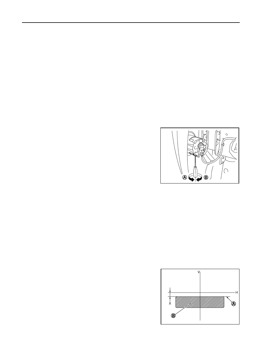
AIMING ADJUSTMENT SCREW

• Turn the aiming adjusting screw for adjustment.

• For the position and direction of the adjusting screw, refer to the

figure.
NOTE:
A screwdriver or hexagonal wrench [6 mm (0.24 in)] can be used
for adjustment.

Aiming Adjustment Procedure

INFOID:0000000009722960

1.

Place the screen.
NOTE:
• Stop the vehicle facing the wall.
• Place the board on a plain road vertically.

2.

Face the vehicle with the screen. Maintain 10 m (32.8 ft) between the front fog lamp center and the
screen.

3.

Start the engine. Illuminate the front fog lamp.

CAUTION:

Never cover the lens surface with a tape etc. The lens is made of resin.
NOTE:
Shut off the headlamp light with the board to prevent from illuminating the adjustment screen.

4.

Adjust the cutoff line height (A) with the aiming adjustment screw so that the distance (X) between the hor-
izontal center line of front fog lamp (H) and (A) becomes 200 mm (7.87 in).

Front fog lamp light distribution on the screen 

A: UP

B: DOWN

JPLIA0811ZZ

JPLIA0008ZZ

FRONT FOG LAMP AIMING ADJUSTMENT

EXL-177

< PERIODIC MAINTENANCE >

[XENON TYPE]

C

D

E

F

G

H

I

J

K

M

A

B

EXL

N

O

P

A

: Cutoff line

B

: High illuminance area

H

: Horizontal center line of front fog lamp

V

: Vertical center line of front fog lamp

X

: Cutoff line height

EXL-178

< REMOVAL AND INSTALLATION >

[XENON TYPE]

FRONT COMBINATION LAMP

REMOVAL AND INSTALLATION

FRONT COMBINATION LAMP

Exploded View

INFOID:0000000009722961

REMOVAL

DISASSEMBLY

1.

Front combination lamp

2.

Headlamp extension panel

JPLIA0812ZZ

1.

Front side marker lamp bulb

2.

Front side marker lamp bulb socket

3.

Resin cap

4.

Seal packing

5.

Xenon bulb socket (Starter)

6.

Xenon bulb

7.

Retaining spring

8.

Seal packing

9.

HID control unit (Inverter)

10.

Parking lamp bulb socket

11. Parking lamp bulb

12. Front turn signal lamp bulb socket

13.

Front turn signal lamp bulb

14. Headlamp housing assembly

Refer to 

GI-4, "Components"

 for symbols in the figure.

JPLIA0813ZZ

FRONT COMBINATION LAMP

EXL-179

< REMOVAL AND INSTALLATION >

[XENON TYPE]

C

D

E

F

G

H

I

J

K

M

A

B

EXL

N

O

P

Removal and Installation

INFOID:0000000009722962

REMOVAL

CAUTION:

Disconnect the battery negative terminal or remove the fuse.

1.

Remove the front grille. Refer to 

EXT-21, "Exploded View"

.

2.

Remove the headlamp extension panel.

3.

Remove the front bumper fascia. Refer to 

EXT-14, "Exploded View"

.

4.

Remove the headlamp mounting bolts.

5.

Remove the harness clips from headlamp housing assembly.

6.

Pull out the headlamp assembly forward the vehicle. 

7.

Disconnect the connector before removing the headlamp assembly. 

INSTALLATION

Install in the reverse order of removal.
NOTE:
After installation, perform aiming adjustment. Refer to 

EXL-173, "Description"

.

Replacement

INFOID:0000000009722963

CAUTION:

• Disconnect the battery negative terminal or remove the fuse.
• After installing the bulb, install the resin cap and the bulb socket securely for watertightness.
• Never touch the glass of bulb directly by hand. Keep grease and other oily matters away from it.
• Never touch bulb by hand while it is lit or right after being turned off.
• Never leave bulb out of lamp reflector for a long time because dust, moisture smoke, etc. may affect

the performance of lamp. When replacing bulb, be sure to replace it with new one.

HEADLAMP BULB

1.

Remove the fender rubber protector in engine room.

2.

Rotate the resin cap counterclockwise and unlock it.

3.

Rotate the bulb socket counterclockwise and unlock it.

4.

Unlock the retaining spring. And then remove the bulb from the
headlamp housing assembly.

CAUTION:

Never break the xenon bulb ceramic tube when replacing
the bulb. 

PARKING LAMP BULB

1.

Rotate the bulb socket counterclockwise and unlock it.

2.

Remove the bulb from the bulb socket.

FRONT TURN SIGNAL LAMP BULB

1.

Remove the front grille.

2.

Rotate the bulb socket counterclockwise and unlock it.

3.

Remove the bulb from the bulb socket.

FRONT SIDE MARKER LAMP BULB

1.

Remove the fender rubber protector in engine room.

2.

Rotate the bulb socket counterclockwise and unlock it.

3.

Remove the bulb from the bulb socket.

JPLIA0814ZZ


содержание   ..  689  690  691  692   ..