содержание .. 507 508 509 510 ..
Nissan Primera P12. Manual - part 509
GW-32
REAR WINDOW DEFOGGER
Rear Window Defogger Circuit Check
EIS0060Y
1.
CHECK FUSE
●
Check 20A fuse [No.7, located in the fuse block (J/B)]
NOTE:
Refer to
GW-16, "Component Parts and Harness Connector Location"
.
OK or NG
OK
>> GO TO 2.
NG
>> If fuse is blown, be sure to eliminate cause of malfunction before installing new fuse, refer to
.
2.
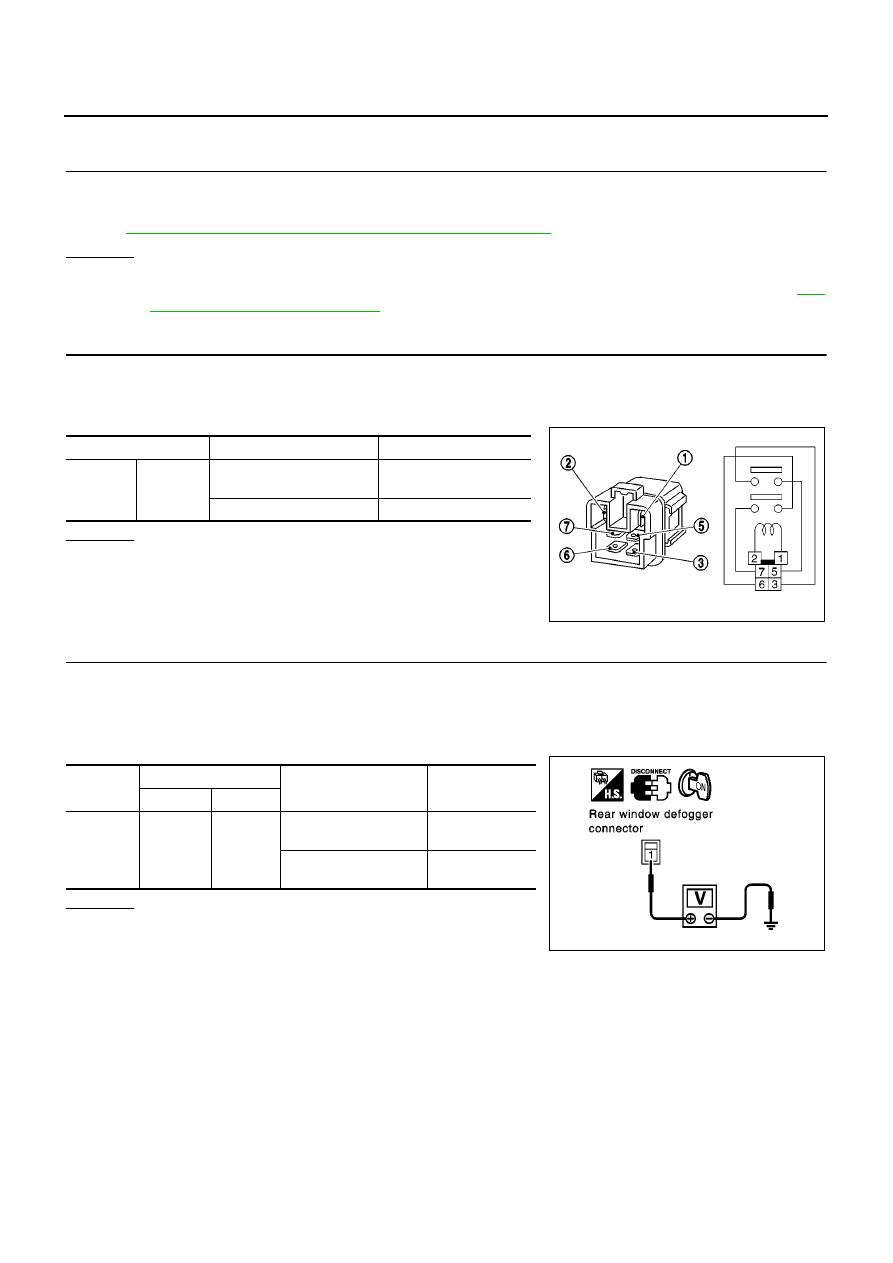
CHECK REAR WINDOW DEFOGGER RELAY
1.
Turn ignition switch OFF.
2.
Remove rear window defogger relay.
3.
Check continuity between rear window defogger terminals 3 and 5.
OK or NG
OK
>> GO TO 3.
NG
>> Replace rear window defogger relay.
3.
CHECK POWER SUPPLY CIRCUIT
1.
Installation rear window defogger relay.
2.
Disconnect rear window defogger connector.
3.
Turn ignition switch ON.
4.
Check voltage between rear window defogger connector and ground.
OK or NG
OK
>> GO TO 4.
NG
>> GO TO 5.
Terminal
Condition
Continuity
3
5
12V direct current supply
between terminals 1 and 2
Yes
No current supply
No
SEC202B
Connector
Terminal (Wire color)
Condition
Voltage (V)
(Approx.)
(+)
(–)
B25
or
B85
1(L/G)
Ground
Rear window defogger
switch ON.
Battery voltage
Rear window defogger
switch OFF.
0
PIIA4234E