Nissan Primera P12. Manual - part 220


  Главная      Nissan     Nissan Primera P12 - Service Manual


поиск по сайту            


содержание   ..  218  219  220  221   ..


Nissan Primera P12. Manual - part 220


TROUBLE DIAGNOSIS

EC-65

[YD (WITH EURO-OBD)]

C

D

E

F

G

H

I

J

K

L

M

A

EC

*: This item includes 1st/2nd trip DTCs.

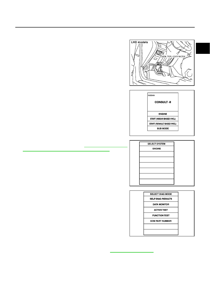
INSPECTION PROCEDURE

1.

Turn ignition switch OFF.

2.

Connect CONSULT-II to data link connector, which is located
under the driver side dash panel.

3.

Turn ignition switch ON.

4.

Touch “START (NISSAN BASED VHCL)”.

5.

Touch “ENGINE”.
If “ENGINE” is not indicated, go to

GI-36, "CONSULT-II Data

Link Connector (DLC) Circuit/For YD Engine Models"

.

6.

Perform each diagnostic test mode according to each service
procedure.

For further information, see the CONSULT-II Operation Manual.

SELF-DIAGNOSTIC MODE
Self Diagnostic Item

Regarding items of DTC and 1st/2nd trip DTC, refer to —

EC-11, "INDEX FOR DTC"

.

MBIB0156E

MBIB0233E

SEF995X

PBIB0410E

EC-66

[YD (WITH EURO-OBD)]

TROUBLE DIAGNOSIS

Freeze Frame Data

DATA MONITOR MODE

Freeze frame data item

Description

DIAG TROUBLE CODE
[PXXXX]

The engine control component part/control system has a trouble code, it is displayed as “PXXXX”.
(Refer to

EC-11, "INDEX FOR DTC"

.)

CAL/LD VALUE [%]

The calculated load value at the moment a malfunction is detected is displayed.

COOLANT TEMP [

°

C] or [

°

F]

The engine coolant temperature at the moment a malfunction is detected is displayed.

ENGINE SPEED [rpm]

The engine speed at the moment a malfunction is detected is displayed.

VEHICL SPEED [km/h] or
[mph]

The vehicle speed at the moment a malfunction is detected is displayed.

INT MANI PRES [kPa]

The intake manifold pressure at the moment a malfunction is detected is displayed.

MONITOR ITEM

ECM

INPUT

SIG-

NAL

MAIN

SIG-

NALS

CAN

DIAG
SUP-

PORT

MNTR

CONDITION

SPECIFICATION

CKPS·RPM (TDC) [rpm]

×

×

The engine speed computed
from the crankshaft position
sensor signal is displayed.

COOLAN TEMP/S
[

°

C] or [

°

F]

×

×

The engine coolant tempera-
ture (determined by the signal
voltage of the engine coolant
temperature sensor) is dis-
played.

When the engine coolant temper-
ature circuit is open or short, ECM
enters fail-safe mode. The engine
coolant temperature determined
by the ECM is displayed.

VHCL SPEED SE
[km/h] or [mph]

×

×

The vehicle speed computed
form the vehicle speed sensor
signal is displayed.

FUEL TEMP SEN
[

°

C] or [

°

F]

×

×

The fuel temperature (deter-
mined by the signal voltage of
the fuel pump temperature sen-
sor) is displayed.

ACCEL POS SEN [V]

×

×

The accelerator pedal position
sensor 1 signal voltage is dis-
played.

ACCEL SEN 2 [V]

×

×

The accelerator pedal position
sensor 2 signal voltage is dis-
played.

ACT CR PRESS [MPa]

×

×

The Fuel rail pressure (deter-
mined by the signal voltage of
the fuel rail pressure sensor) is
displayed.

BATTERY VOLT [V]

×

×

The power supply voltage of
ECM is displayed.

P/N POSI SW [ON/OFF]

×

×

Indicates [ON/OFF] condition
from the park/neutral position
switch signal.

START SIGNAL [ON/OFF]

×

×

indicates [ON/OFF] condition
from the starter signal.

PW/ST SIGNAL [ON/OFF]

×

indicates [ON/OFF] condition
from the power steering pres-
sure switch signal.

[OFF] is always displayed for
models without power steering
pressure switch.

BRAKE SW [ON/OFF]

×

×

indicates [ON/OFF] condition
from the stop lamp switch sig-
nal.

TROUBLE DIAGNOSIS

EC-67

[YD (WITH EURO-OBD)]

C

D

E

F

G

H

I

J

K

L

M

A

EC

BRAKE SW2 [ON/OFF]

×

×

indicates [ON/OFF] condition
from the ASCD brake switch
and ASCD clutch switch signal.

IGN SW [ON/OFF]

×

×

Indicates [ON/OFF] condition
from ignition switch signal.

MAS AIR/FL SE [V]

×

×

The signal voltage of the mass
air flow sensor is displayed.

MAIN INJ WID [msec]

×

Indicates the actual fuel injec-
tion pulse width compensated
by ECM according to the input
signals.

PUMP CURRENT [mA]

×

Indicates the fuel pump power
supply current from the ECM.

GLOW RLY [ON/OFF]

×

The glow relay control condition
(determined by ECM according
to the input signal) is displayed.

COOLING FAN

[LOW/HI/OFF]

×

Indicates the control condition of
the cooling fans (determined by
ECM according to the input sig-
nal).
LOW ... Operates at low speed.
HI ... Operates at high speed.
OFF ... Stopped

EGR VOL CON/V [step]

×

Indicates the EGR volume con-
trol value computed by the ECM
according to the input signals.

The opening becomes larger as
the value increases.

INT/A VOLUME [mg/]

The intake air volume computed
from the mass air flow sensor
signal is displayed.

BARO SEN [kPa]

×

×

The barometric pressure (deter-
mined by the signal voltage from
the absolute pressure sensor
built into the ECM) is displayed.

INT/M PRES SE [kPa]

Turbocharger boost (determined
by the signal voltage from the
turbocharger boost sensor) is
displayed.

CYL COUNT [1/2/3/4]

The cylinder being injected is
displayed.
1 ... Cylinder No.1 is injected.
2 ... Cylinder No.2 is injected.
3 ... Cylinder No.3 is injected.
4 ... Cylinder No.4 is injected.

SET SW
[ON/OFF]

×

Indicates [ON/OFF] condition
from SET/COAST switch signal.

RESUME/ACC SW
[ON/OFF]

×

Indicates [ON/OFF] condition
from RESUME/ACCEL switch
signal.

CANCEL SW
[ON/OFF]

×

Indicates [ON/OFF] condition
from CANCEL switch signal.

MONITOR ITEM

ECM

INPUT

SIG-

NAL

MAIN

SIG-

NALS

CAN

DIAG
SUP-

PORT

MNTR

CONDITION

SPECIFICATION

EC-68

[YD (WITH EURO-OBD)]

TROUBLE DIAGNOSIS

NOTE:
Any monitored item that does not match the vehicle being diagnosed is deleted from the display automatically.

ACTIVE TEST MODE

MAIN SW
[ON/OFF]

×

Indicates [ON/OFF] condition
from ON/OFF switch signal.

Voltage [V]

Voltage, frequency, duty cycle or
pulse width measured by the
probe.

Only “#” is displayed if item is
unable to be measured.
Figures with “#”s are temporary
ones.
They are the same figures as an
actual piece of data which was
just previously measured. [Hz] or
[%]

Frequency [msec], [Hz] or
[%]

DUTY-HI

DUTY-LOW

PLS WIDTH-HI

PLS WIDTH-LOW

CAN COMM
[OK/NG]

×

Indicates the communication
condition of CAN communica-
tion line.

These items are not displayed
in “SELECTION FROM MENU”
mode.

CAN CIRC 1
[OK/UNKWN]

×

CAN CIRC 2
[OK/UNKWN]

×

CAN CIRC 3
[OK/UNKWN]

×

CAN CIRC 4
[OK/UNKWN]

×

CAN CIRC 5
[OK/UNKWN]

×

CAN CIRC 6
[OK/UNKWN]

×

CAN CIRC 7
[OK/UNKWN]

×

MONITOR ITEM

ECM

INPUT

SIG-

NAL

MAIN

SIG-

NALS

CAN

DIAG
SUP-

PORT

MNTR

CONDITION

SPECIFICATION

TEST ITEM

CONDITION

JUDGEMENT

CHECK ITEM (REMEDY)

POWER BAL-
ANCE

Engine: After warming up, idle the
engine.

A/C switch: OFF

Shift lever: N

Cut off each injector signal one at
a time using CONSULT-II

Engine runs rough or dies.

Harness and connectors

Compression

Fuel injector

COOLING FAN *

Ignition switch: ON

Operate the cooling fan at LOW,
HI speed and turn OFF using
CONSULT-II.

Cooling fan moves at LOW, HI
speed and stops.

Harness and connector

Cooling fan motor

Cooling fan relay

ENG COOLANT
TEMP

Engine: Return to the original
trouble condition

Change the engine coolant tem-
perature using CONSULT-II.

If trouble symptom disappears, see
CHECK ITEM.

Harness and connectors

Engine coolant temperature sen-
sor

Fuel injector

GLOW RLY

Ignition switch: ON (Engine
stopped)

Turn the glow relay ON and OFF
using CONSULT-II and listen to
operating sound.

Glow relay makes the operating
sound.

Harness and connector

Glow relay


содержание   ..  218  219  220  221   ..