содержание .. 119 120 121 122 ..
Nissan Primera P12. Manual - part 121
FRONT DISC BRAKE
BR-23
C
D
E
G
H
I
J
K
L
M
A
B
BR
FRONT DISC BRAKE
PFP:41000
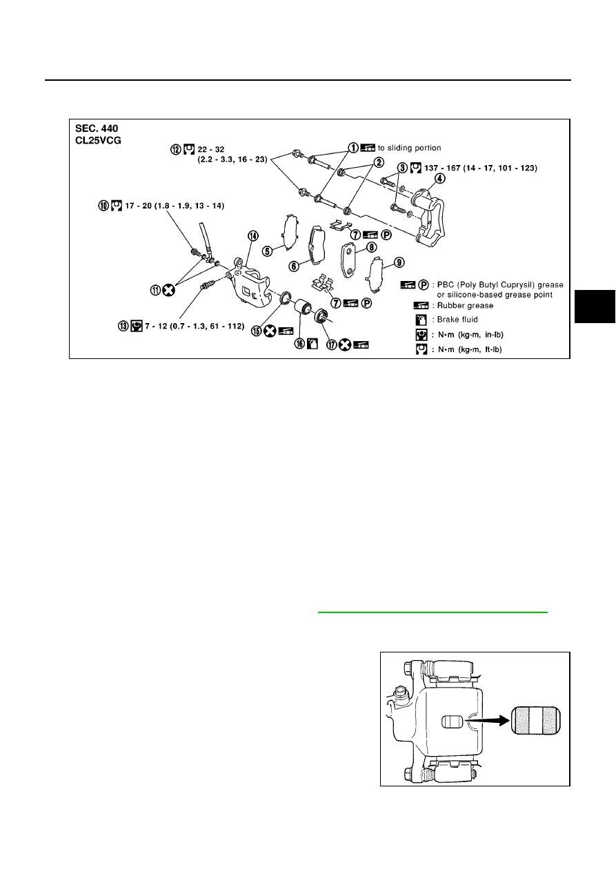
Component
EFS002V8
WARNING:
●
Clean brake pads with a vacuum dust collector to minimize the hazard of airborne particles or
other materials.
CAUTION:
●
When cylinder body is open, do not depress brake pedal because piston will pop out.
●
Be careful not to damage piston boot or get oil on rotor. Always replace shims when replacing
pads.
●
If shims are rusted or show peeling of the rubber coat, replace them with new shims.
●
It is not necessary to remove connecting bolt except for disassembly or replacement of caliper
assembly. In this case, suspend cylinder body with wire so as not to stretch brake hose.
●
Burnish the brake contact surfaces after refinishing or replacing rotors, after replacing pads, or if
a soft pedal occurs at very low mileage. Refer to
BR-27, "BRAKE BURNISHING PROCEDURE"
.
Inspection
EFS002V9
PAD THICKNESS
Check pad thickness by lifting vehicle, removing the wheel, and look-
ing through check hole on cylinder body. If necessary, use a scale.
SFIA0480E
1.
Main pin
2.
Pin boot
3.
Torque member fixing bolt
4.
Torque member
5.
Inner shim
6.
Inner pad
7.
Pad retainer
8.
Outer pad
9.
Outer shim
10. Connecting bolt
11. Copper washer
12. Main pin bolt
13. Bleed valve
14. Cylinder body
15. Piston seal
16. Piston
17. Piston boot
Standard pad thickness
: 11 mm (0.43 in)
Pad wear limit
: 2.0 mm (0.079 in)
BRA0010D