содержание .. 114 115 116 117 ..
Nissan Primera P12. Manual - part 116
PRECAUTIONS
BR-3
C
D
E
G
H
I
J
K
L
M
A
B
BR
PRECAUTIONS
PFP:00001
Precautions for Models with SRS Air Bag and Pre-Tensioner Seat Belt
EFS002UM
WARNING:
●
Before removing and installing components and harnesses of SRS air bag and seat belt pre-
tensioner system, turn ignition switch OFF, disconnect battery ground cable, and wait at least 3
minutes. (This discharges electricity held in the air bag sensor unit's additional power circuit.)
●
Do not use pneumatic or electric tools to remove and install the components.
●
Do not solder SRS air bag and seat belt pre-tensioner system harnesses when making repairs.
Make sure harness is not pinched and there is no contact with other components.
●
When checking the SRS air bag and the seat belt pre-tensioner circuit or the components of each
system, do not use an electric tester such as a circuit tester. (This is to prevent accidental trigger-
ing caused by the weak electric current of a tester.)
●
Never insert foreign material (such as a screwdriver) in the air bag module and pre-tensioner seat
belt connectors. (The units may be actuated by mistake by static electricity.)
●
Seat belt pre-tensioner and SRS air bag harnesses can be distinguished from other harnesses by
their yellow connectors.
●
When servicing, refer to “SB Seat Belt” and “SRS Air Bag” for safety.
Precautions for Brake System
EFS002UN
●
Clean dust on brake pads, shoes, drums, and back plates with a vacuum dust collector. Do not blow with
compressed air.
●
Recommended fluid is brake fluid “DOT 3” or “DOT 4”.
●
Never reuse drained brake fluid.
●
Be careful not to splash brake fluid on painted areas such as the body. If brake fluid is splashed or spilled
on paint, wipe it off and flush the area with water immediately.
●
Use only clean brake fluid when cleaning master cylinder and disc brake components.
●
Never use mineral oils such as gasoline or kerosene to clean. They will ruin the rubber parts and cause
improper operation.
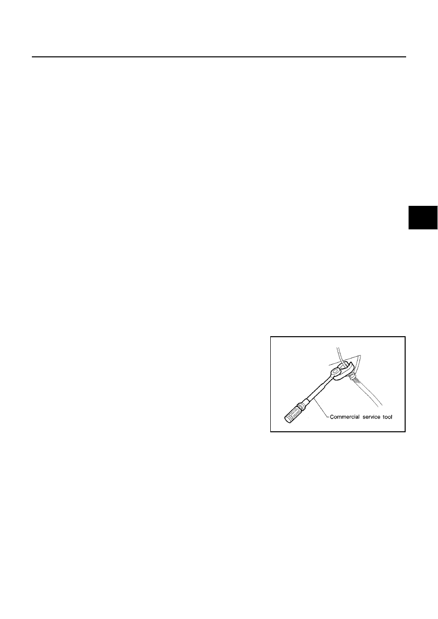
●
Always use a flare nut torque wrench to securely tighten brake
tube flare nuts.
●
The brake system is an important safety part. If a brake fluid
leak is detected, always disassemble the related parts. If dam-
age,deformation or excessive wear is detected, replace affected
parts with new ones.
●
Before staring operation, be sure to turn the ignition switch OFF
and disconnect the ABS actuator and control module connector
or battery cables.
●
When installing brake piping, be sure to check torque.
SBR686C